
In this guide, we shall investigate how to use timer to generate precise delay in down to microseconds ( will use 1 second delay here for demonstrations purposes only).
In this guide, we will cover the following:
- What is the timer and how it works
- Configure the timer to generate delay
- Code
- Demo
1 What is the timer and how it works
A Timer Module in its most basic form is a digital logic circuit that counts up every clock cycle. More functionalities are implemented in hardware to support the timer module so it can count up or down. It can have a Prescaler to divide the input clock frequency by a selectable value. It can also have circuitry for input capture, PWM signal generation, and much more as we’ll see in this tutorial.
Let’s consider a basic 16-Bit timer like the one shown below. As a 16-Bit time, it can count from 0 up to 65535. Every clock cycle, the value of the timer is incremented by 1. And as you can see, the Fsys is not the frequency that is incrementing the timer module. But it gets divided by the Prescaler, then it gets fed to the timer.
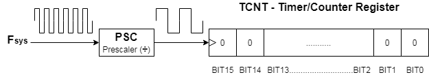
Basically, in timer mode, the TCNT register is incremented by 1 each clock cycle @ the following frequency (Fsys/PSC). This means if the Fsys is 80MHz & PSC is 1:1024, the TCNT gets incremented by 1 every 12.8μSec. Therefore, if you start this timer to count from 0 until it reaches overflow (at 65535), a flag will be set and starts over from zero
2. Configure the timer to generate delay
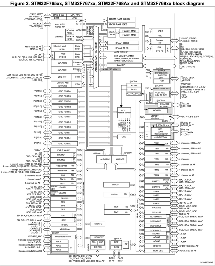
We starting by getting to know which timer to use, in this case , we will use TIMER2.
Hence, we need to know which bus is connected to. From the diagram, TIMER2 is connected to APB1 bus
Then we enable clock access to the timer as following:
RCC->APB1ENR|=RCC_APB1ENR_TIM2EN;
After we enabled clock access to TIM2 we shall set the prescaller and auto-reload value as following:
TIM2->PSC=16000-1; //16 000 000 Hz / 16 000 = 1 000 Hz
TIM2->ARR=1000-1;   // 1000 Hz/ 1000 = 1 Hz
The ARR value is the maximum value can the counter counts. Since TIM2 is 32-bit timer, it can counts up to (2^32 -1 = 4294967295).
now we enable timer as following:
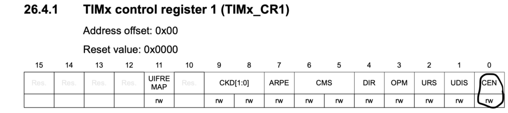
TIM2->CR1=TIM_CR1_CEN;
For delay purposes, we shall wait to the UIF to be set in SR register then reset it as following
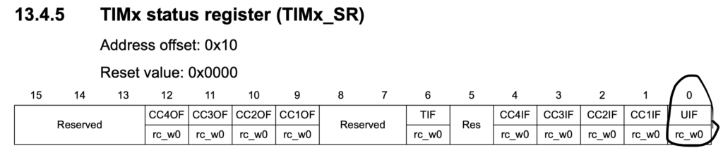
while(!(TIM2->SR&TIM_SR_UIF)){} //wait UIF to be set
		TIM2->SR&=~TIM_SR_UIF; //reset UIF
Then we can toggle the LED
GPIOB->ODR^=GPIO_ODR_OD7;
3. Code:
The code shall be this for timer delay to blink an LED each second
For how to enable the build-in LED, you can check this guide (Getting started with STM32F7: Blinking LED)
#include "stm32f7xx.h"                  // Device header

int main(void)
	{
	//enable clock access to GPIOB
		RCC->AHB1ENR|=RCC_AHB1ENR_GPIOBEN;
	//set PB7 as output
		GPIOB->MODER|=GPIO_MODER_MODER7_0;
		GPIOB->MODER&=~GPIO_MODER_MODER7_1;
	//timer2 configure
		RCC->APB1ENR|=RCC_APB1ENR_TIM2EN;
		TIM2->PSC=16000-1; //16 000 000 Hz / 16 000 = 1 000 Hz
		TIM2->ARR=1000-1;   // 1000 Hz/ 1000 = 1 Hz
		TIM2->CNT=0;
		TIM2->CR1=TIM_CR1_CEN;


	while(1)
		{
		//set PB7 to high
		GPIOB->ODR^=GPIO_ODR_OD7;
		while(!(TIM2->SR&TIM_SR_UIF)){} //wait UIF to be set
		TIM2->SR&=~TIM_SR_UIF; //reset UIF
		}
	}
Add Comment