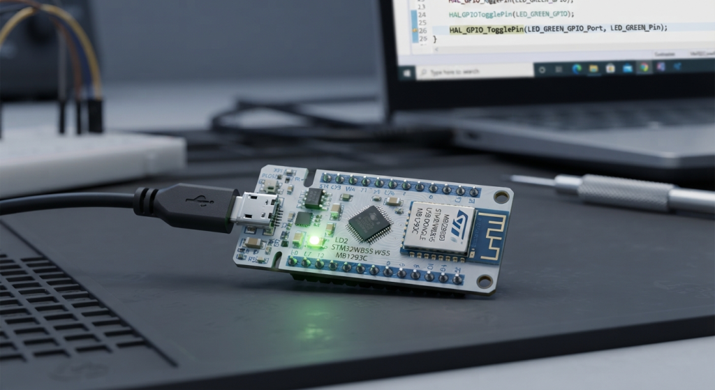
In Part 2 of our series, we will configure the STM32WB55 to initialize its Bluetooth Low Energy stack and start broadcasting advertising packets. You’ll then learn how to detect the device and establish an active connection directly from your smartphone using a BLE scanner app.
In this guide, we shall cover the following:
- Introduction.
- STM32CubeMX setup.
- Firmware Development.
- Results.
1. Introduction:
Before writing a single line of radio firmware or launching a mobile scanner app, it is crucial to understand the fundamental mechanics that make Bluetooth Low Energy so efficient. BLE was designed from the ground up to achieve ultra-low power consumption by keeping the radio turned off as much as possible. It replaces the continuous connection model of classic Bluetooth with an asynchronous, event-driven architecture centered around discovery, broadcasting, and precise connection windows.
In this installment, we will demystify the Generic Access Profile (GAP), break down how BLE devices format their broadcast payloads, examine the underlying Host-Controller architecture, and trace the exact lifecycle of establishing a mobile connection.
Generic Access Profile (GAP) & Discovery Architecture
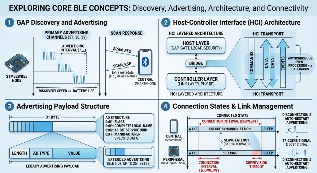
The Generic Access Profile (GAP) forms the operational foundation of any BLE system. It defines how devices announce their presence, discover nearby nodes, and establish point-to-point connections. GAP categorizes devices into distinct roles depending on their operational goal:
- Broadcaster vs. Observer: A non-connectable topology where a node unidirectionally broadcasts data (such as a temperature sensor or beacon) without accepting incoming links, while an Observer passively listens to those packets.
- Peripheral vs. Central: A connectable topology. The Peripheral (typically a resource-constrained node or sensor) advertises its availability, while the Central device (such as a smartphone, gateway, or tablet) actively scans for peripherals and initiates connections.
To handle RF interference in busy 2.4 GHz environments shared with Wi-Fi and classic Bluetooth, BLE divides the 2.4 GHz spectrum into 40 distinct 2 MHz channels. Three of these—Channels 37, 38, and 39—are explicitly designated as Primary Advertising Channels. These channels are strategically spaced across the spectrum to sit in the quiet guard bands between common Wi-Fi channels, ensuring high discoverability.
A Peripheral advertises by transmitting small broadcast packets across Channels 37, 38, and 39 in rapid succession. The timing between these transmission events is known as the Advertising Interval (Tadv). Tuning this interval is a fundamental design trade-off:
- Aggressive Advertising (20 ms – 100 ms): Results in near-instant discovery by smartphones, but draws higher average power.
- Low-Power Advertising (1 sec – 2.5 sec): Drastically reduces power consumption to microamp levels, but increases the time a smartphone takes to discover the device.
Additionally, GAP supports an Active Scanning mechanism. When a Central device detects an advertisement packet, it can transmit a SCAN_REQ frame back to the Peripheral during a tiny listening window. The Peripheral then responds with a SCAN_RSP packet, allowing it to send an additional 31 bytes of metadata—such as a full human-readable device name or custom manufacturer information—without establishing an active connection.
Host-Controller Interface (HCI) & Architecture
To keep real-time RF timing isolated from complex user applications, modern BLE stacks separate software tasks into two distinct functional layers: the Host and the Controller.
+-------------------------------------------------------+
|                     APPLICATION                       |
+-------------------------------------------------------+
|                        HOST                           |
|       (GAP / GATT / L2CAP / Security Manager)         |
+-------------------------------------------------------+
|               HOST-CONTROLLER INTERFACE               |
|                         (HCI)                         |
+-------------------------------------------------------+
|                     CONTROLLER                        |
|              (Link Layer / Physical RF)               |
+-------------------------------------------------------+
- The Host Layer: Resides on the main application processor. It manages high-level logic, including GAP (device discovery and roles), GATT (data structuring and services), Security Manager (pairing and encryption), and L2CAP (data multiplexing).
- The Controller Layer: Runs directly on dedicated radio hardware or a low-level co-processor. It handles time-critical task management, frequency hopping, packet framing, CRC checks, and Physical Layer (PHY) RF transmissions.
- The Host-Controller Interface (HCI): A standardized communication protocol layer that sits between the Host and Controller. The Host sends asynchronous commands (e.g., “Start Advertising”) down to the Controller via HCI, and the Controller sends asynchronous status events (e.g., “Connection Completed”) back up to the Host.
Because BLE stack operations are non-blocking and event-driven, the application CPU does not spin in execution loops waiting for radio responses. Instead, the MCU sits in a low-power sleep state until an HCI interrupt or callback wakes the system to handle incoming packet events.
Advertising Payload Structure
Every piece of data broadcast by a BLE Peripheral must strictly adhere to the standardized packet structures defined by the Bluetooth SIG. In legacy BLE 4.2, the raw payload of an advertising packet is capped at 31 bytes (expanded up to 254 bytes in BLE 5.0 Extended Advertising).
Inside this 31-byte limit, data is organized into self-contained blocks known as AD Structures (Advertising Data Structures). Each structure uses a Length-Type-Value (LTV) formatting scheme:
- Length (1 Byte): Specifies the total byte count of the AD Type and Payload that follow.
- AD Type (1 Byte): Identifies the category of data being transmitted. Common types include:
0x01: Flags (e.g., General Discoverable Mode, BR/EDR Not Supported).0x09: Complete Local Name (human-readable string like"My BLE Node").0x02/0x03: 16-bit Service UUIDs (notifying scanners of supported GATT services).0xFF: Manufacturer Specific Data (custom vendor payloads).
- Value (Variable): The raw data bytes corresponding to the AD Type.
By evaluating these AD structures during a scan, Central devices can filter discovered hardware based on company IDs, offered services, or target names before deciding to initiate a connection.
Connection States & Link Management
When a smartphone or Central device decides to connect to a Peripheral, it waits for the next advertisement packet and sends a CONNECT_IND request on the same channel. At this point, the Peripheral halts advertising, and both devices transition into a point-to-point Connected State.
Once connected, data is no longer broadcast publicly; instead, communication occurs during dedicated, synchronized transmission windows defined by several key parameters:
- Connection Interval (CONN_INT): The precise time delay between consecutive data exchange windows (ranging from 7.5 ms to 4 seconds). Both devices wake up synchronously, exchange data frames, and immediately go back to sleep.
- Slave Latency: The number of consecutive connection intervals that the Peripheral is allowed to skip if it has no new data to send. This lets the Peripheral keep its radio off even if the Central wakes up frequently.
- Supervision Timeout: The maximum time allowed between valid packet exchanges before the link is considered lost, triggering a disconnect.
When a disconnection occurs (whether triggered by user command or signal loss), stack callbacks report a disconnection event back to the Host application. This allows the firmware to update its state machine, update physical status indicators, and automatically restart advertising so new Central devices can connect.
2. STM32CubeMX Setup:
We shall continue from the previous guide here.
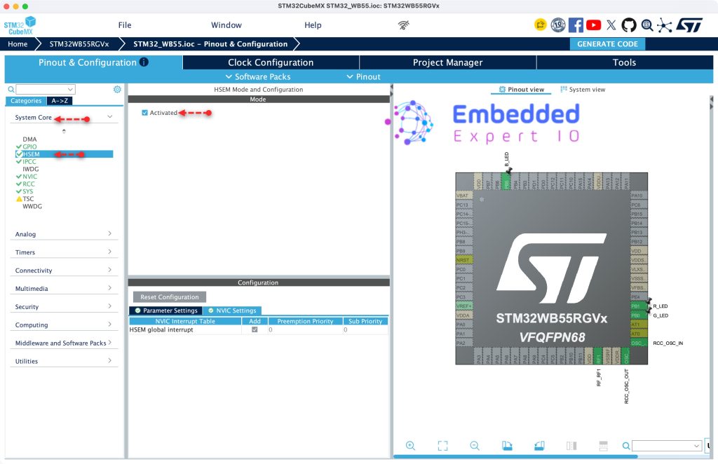
First, from System Core, enable HSEM (Hardware Semaphore) as follows:
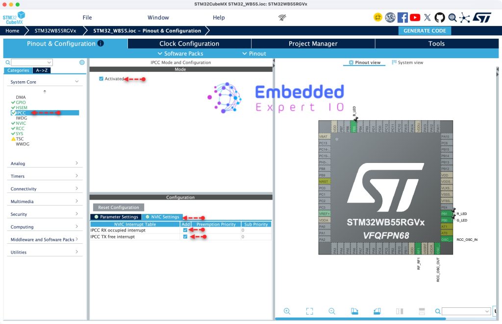
Next, enable IPPC and related interrupt as follows:
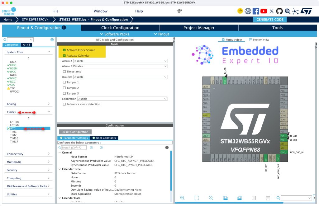
Next, from timers, enable RTC and calendar as follows:
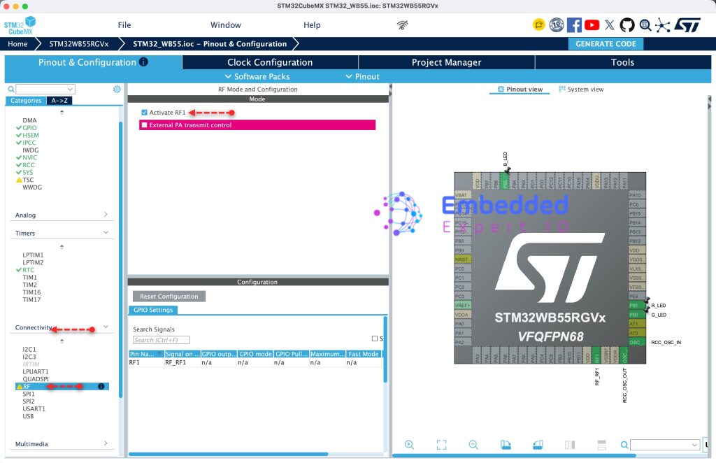
Next, from Connectivity, enable RF module as follows:
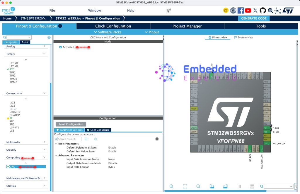
Next, from Computing, enable CRC as follows:
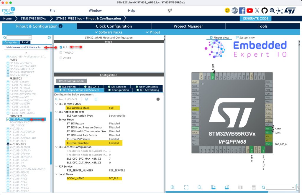
Next, from Middleware and Software Package, STM32_WPAN, select BLE and configure it as follows:
- BLE Wireless Stack is set to Full.
- Custom Template to Enabled.
- Set the LOCAL_NAME to MY_BLE.
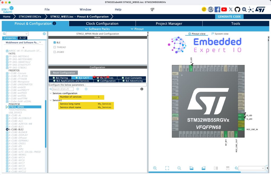
Next, from BLE GATT:
- Number of Services to 1.
- Short and long name to My_Services (You can choose your own).
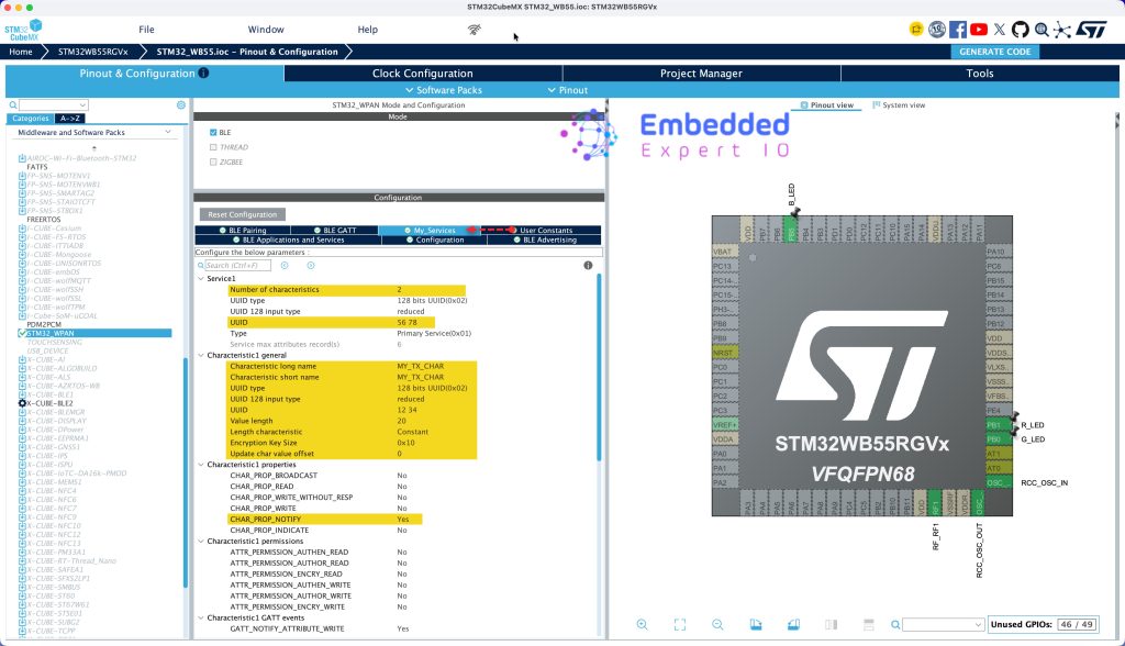
Next, from MY_SERVICES tab (Or what ever the name you gave to the services):
- Set number of characters to 2.
- Set UUID to 56 78
For Characteristic 1 general:
- Short and long Name as MY_TX_CHAR
- UUID to 12 34
- Value length to 20
- From properties, set it to Notify.
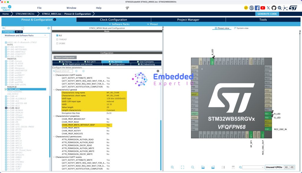
For characteristics 2:
- Short and long name to MY_RX_CHAR.
- UUID 12 35
- Value length to 20
- Properties to Write without response.
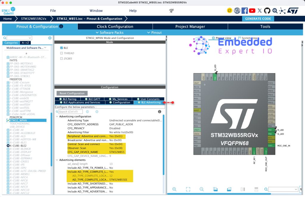
Next, from BLE advertising:
- Set peripheral advertise and connect to yes.
- Central Scan and connect to yes.
- Observer scan to yes.
- Set to CGF_GAP_DEVICE_NAME STM32WB55
- Enable Include AD_TYPE_COMPLETE_NAME and set it to STM32WB55EE (This name shall appear when scan for BLE).
Thats all for the configuration.
Click on generate code and this will generate the project.
3. Firmware Development:
Open the project in STM32CubeIDE.
From Core/inc open app_conf.h header file.
In user code begin Generic_Parameters, declare the following:
#define ADV_TYPE     0
#define ADV_FILTER    0
Thats all for the firmware.
Save, build the project and run it as follows:

You may download the project from our github repository from here.
4. Results:
Using LightBlue app on your phone, you can connect to STM32WB55EE as follows:
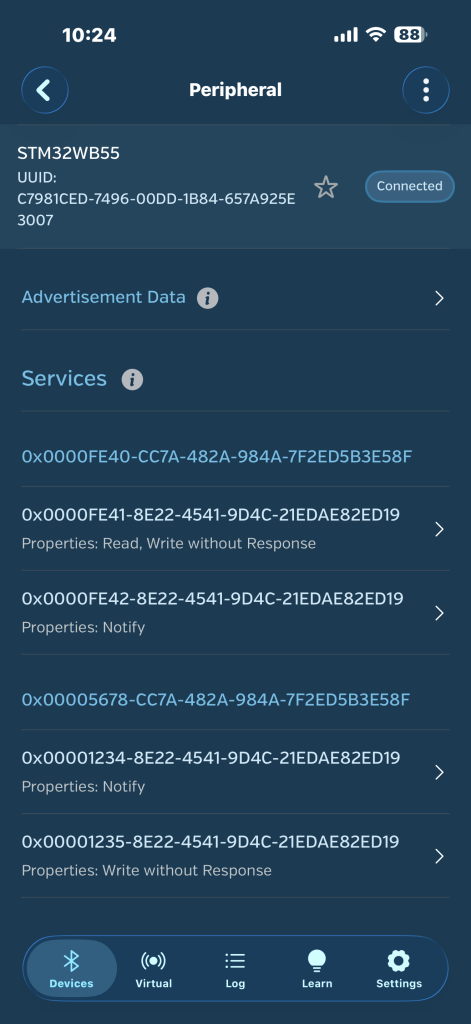
Note the second services, 1234 and 1235, they are the characteristics we declare in STM32CubeMX.
Next part, we shall develop the application to send and receive data to/from smartphone.
Stay tuned.
Happy coding 😉

Add Comment