

Taking data acquisition to the ultimate level of efficiency, this guide explores using Direct Memory Access (DMA) to capture continuous single-channel ADC conversions on the STM32F4. By configuring the DMA controller alongside the LL drivers, the ADC autonomously streams conversion results directly into a memory buffer, completely eliminating CPU intervention and maximizing system throughput.
Int this guide, we shall cover the following:
- Introduction.
- STM32CubeMX configuration.
- Firmware development.
- Results.
1. Introduction:
As we progress in our mastery of the STM32F4’s Analog-to-Digital Converter, we arrive at the absolute pinnacle of data acquisition efficiency: Direct Memory Access (DMA). While our previous guide utilized continuous mode with interrupts to achieve a non-blocking design, that approach still relies heavily on the CPU to facilitate every single data transfer. When dealing with high-frequency, continuous analog signals, even optimized LL interrupt service routines can become a bottleneck. To truly unleash the microcontroller’s potential, we must decouple the data transfer process from the CPU entirely.
To understand why DMA is the ultimate solution for continuous conversion, we must look at the evolution of data acquisition strategies on microcontrollers: Polling, Interrupts, and DMA.
The Evolution of Data Acquisition: Polling vs. Interrupts vs. DMA
1. Polling: The Blocking Approach
In the single-conversion polling method, the CPU initiates the ADC and enters a while loop, actively checking the End-of-Conversion (EOC) status register.
- The Good: It is the simplest method to implement and requires no complex configuration.
- The Bad: It is highly inefficient. While waiting for the conversion to finish, the CPU cannot perform any other tasks. In a continuous mode scenario, the CPU would be trapped in an infinite loop of reading data, leaving zero bandwidth for control algorithms, communication stacks, or user interfaces.
2. Interrupts: The Non-Blocking, Context-Switching Approach
By enabling continuous mode and utilizing interrupts, the CPU is freed from the waiting loop. The ADC converts data autonomously in the background; upon completion, it fires a hardware interrupt. The CPU briefly suspends its main task, jumps to an Interrupt Service Routine (ISR) to read the data register, and resumes its main program.
- The Good: Non-blocking design allows multitasking. The CPU only spends time on the ADC when new data is actually available.
- The Bad: Context switching overhead. Every time an interrupt fires, the Cortex-M4 core must save its current state to the stack, execute the ISR, and restore the state. If the ADC is in continuous mode running at high speeds (e.g., hundreds of thousands of samples per second), the CPU will be bombarded with interrupts. It will spend all its time entering and exiting ISRs, leading to stack overflow or system lockup, leaving no time to actually process the data.
3. DMA: The Autonomous Hardware Approach
Direct Memory Access (DMA) is a dedicated hardware controller built into the STM32F4 specifically designed to move data between peripherals (like the ADC) and memory (RAM) without any CPU intervention. You configure the DMA stream with a source address (the ADC data register), a destination address (a RAM array/buffer), and a transfer count. The DMA controller then autonomously fetches each ADC conversion and places it into your memory buffer.
- The Good: Zero CPU overhead during data transfer. The CPU is completely unaware of the ADC’s continuous conversions and can dedicate 100% of its cycles to processing the data or running other tasks. You can even configure the DMA to trigger an interrupt only when a specific buffer is “half-full” or “completely full,” allowing the CPU to process data in large, efficient blocks (double-buffering).
- The Bad: It is the most complex to configure, requiring a deep understanding of the STM32F4’s DMA multiplexer, stream routing, and peripheral-to-memory arbitration.
Why LL Drivers are Essential for ADC + DMA
While the HAL library can configure ADC with DMA, it wraps the DMA transfers in complex state-machine callbacks and hidden management functions. This introduces latency and defeats the purpose of a raw, high-speed hardware pipeline.
By utilizing the LL Drivers, we strip away the abstraction. We will directly configure the DMA stream’s channel, set the peripheral and memory addresses, configure the data widths, and enable the Circular mode for continuous data streaming. We will then directly link this DMA stream to the ADC’s hardware DMA request. The result is a lean, bare-metal, high-speed data pipeline that streams continuous analog data straight into your RAM arrays with absolute minimal setup overhead and zero ongoing CPU interference.
In the following sections, we will configure the ADC in continuous mode, set up the DMA controller using LL drivers, and establish a highly efficient circular buffer to capture our analog data in the background.
Related course
Build the LL ADC and DMA connection
After comparing polling, interrupts and DMA, explore the LL acquisition-driver workflow. Build a broader foundation in STM32 Low-Layer driver development. The course covers GPIO, UART, timers, ADC, interrupts, DMA, I2C and SPI, with a consistent approach to reading peripheral documentation and connecting configuration to working firmware.
2. STM32CubeMX Configuration:
We shall continue from here.
Open the .ioc project file in STM32CubeMX.
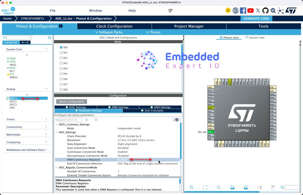
From Analog, ADC1, set DMA continuous Request to enabled as follows:
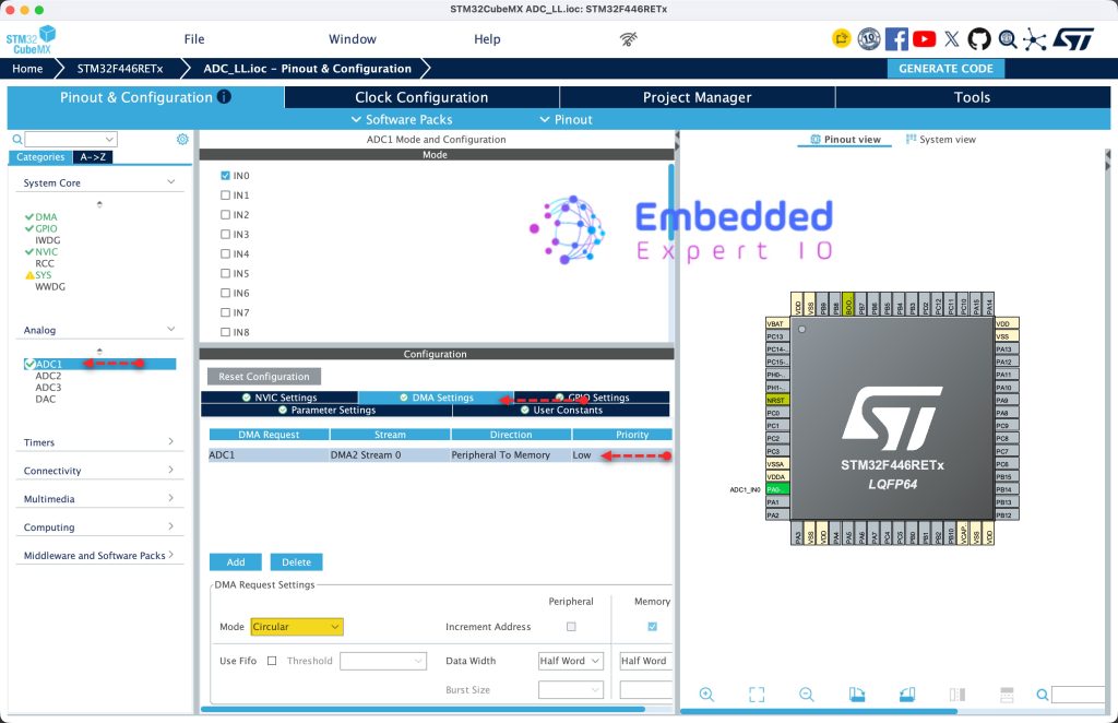
Next, from DMA Settings, enable DMA channel and set mode to circular as follows:
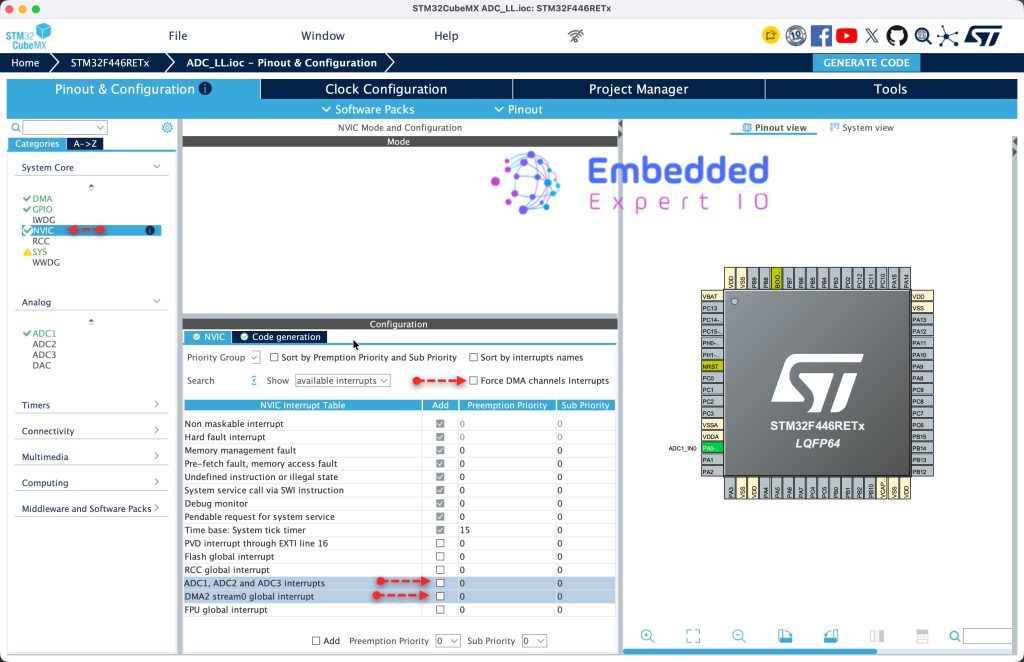
Next, from System Core, NVIC, uncheck Force DMA interrupt and disable interrupt for ADC and DMA as follows:
Next, from Project Manager, Advanced, set DMA to LL and click on Generate code as follows:
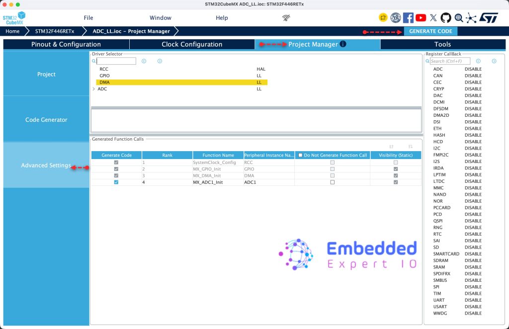
Thats all for the configuration.
3. Firmware Development:
Open the project from STM32CubeIDE.
Open adc.h header file.
In user code begin Prototypes, declare the following function:
void ADC_Start_DMA_SingleCHannel(uint16_t *adcBuff);
This function shall start the ADC with DMA and convert for single shall. It takes pointer to where to store the converted data.
Next, open adc.c source file.
In user code begin 1, we shall build the function.
void ADC_Start_DMA_SingleCHannel(uint16_t *adcBuff)
Within the function:
Disable the DMA stream and wait until it is disabled as follows:
LL_DMA_DisableStream(DMA2, LL_DMA_STREAM_0);
while (LL_DMA_IsEnabledStream(DMA2, LL_DMA_STREAM_0));
Please note that you need to use same DMA and Stream you configured in STM32CubeMX.
Next, set the peripheral address to be ADC1 regular register as follows:
LL_DMA_SetPeriphAddress(DMA2, LL_DMA_STREAM_0, LL_ADC_DMA_GetRegAddr(ADC1, LL_ADC_DMA_REG_REGULAR_DATA));
Next, set the number of transfers to 1 since we have single channel.
LL_DMA_SetDataLength(DMA2, LL_DMA_STREAM_0, 1);
Set the memory address to the address passed by the user as follows:
LL_DMA_SetMemoryAddress(DMA2, LL_DMA_STREAM_0, (uint32_t)adcBuff);
Next, start the DMA stream:
LL_DMA_EnableStream(DMA2, LL_DMA_STREAM_0);
Finally, start the ADC and conversion as follows:
LL_ADC_Enable(ADC1);
LL_ADC_REG_StartConversionSWStart(ADC1);
Next, in main.c file, in user code begin 1 in main function, start the conversion in DMA mode:
ADC_Start_DMA_SingleCHannel(&adc_value);
Thats all for the firmware.
Save, build the project and run it as follows:

You may download the project from our github repository from here.
4. Results
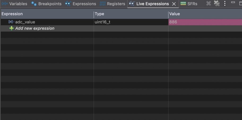
Open a debugging session, add adc_value to live expression, you should get something like this:
Thats all for this guide.
Next, we shall enable multiple channels and use DMA to acquire the data.
Stay tuned.
Happy coding 😉
Discussion