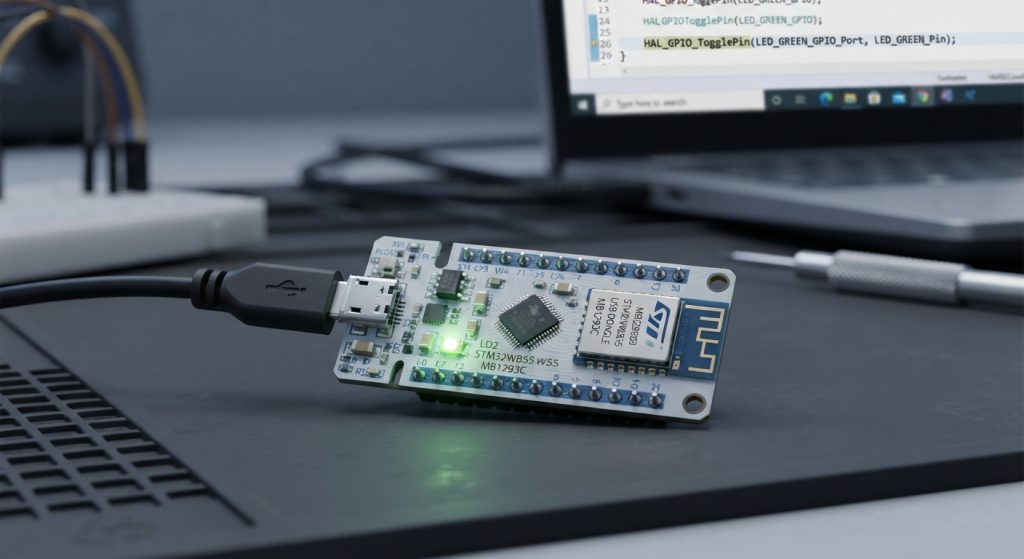
In Part 1 of our BLE application development series for the STM32WB55! In this guide, we will explore the key features of the STM32WB55, introduce core Bluetooth Low Energy concepts, and configure a basic GPIO to blink an LED as our first step toward building a complete wireless application.
In this guide, we shall cover the following:
- Introduction.
- STM32CubeMX setup.
- Importing the project to STM32CubeIDE.
- Firmware Development.
- Results.
1. Introduction:
Welcome to Part 1 of our comprehensive BLE application development series for the STM32WB55! As the Internet of Things (IoT) continues to expand, ultra-low-power wireless connectivity has become a cornerstone of modern embedded system design. Among the myriad of wireless protocols available, Bluetooth Low Energy (BLE) stands out as the industry standard for short-range communication, wearable devices, smart home automation, and industrial sensor nodes.
In this series guide, we will transition you from a complete beginner to a confident developer capable of building robust, custom wireless applications. For this first step, we will explore the powerful hardware features of the STM32WB55 microcontroller, provide a foundational overview of BLE concepts, and lay our groundwork by configuring a basic General-Purpose Input/Output (GPIO) pin to blink an LED as a hardware sanity check.
Understanding the STM32WB55 Microcontroller
The STM32WB55 is an advanced, ultra-low-power dual-core wireless microcontroller from STMicroelectronics designed to handle both heavy application processing and strict real-time wireless stack operations concurrently.
- Dual-Core Architecture: It features an Arm Cortex-M4 core running at 64 MHz, dedicated to managing the user application logic, peripherals, and sensors. Alongside it sits an Arm Cortex-M0+ core running at 32 MHz, which exclusively handles the radio and Bluetooth/802.15.4 stack, ensuring your application code never interferes with critical radio timing.
- Multi-Protocol Wireless Radio: The integrated 2.4 GHz radio supports Bluetooth Low Energy (BLE 5.3), Zigbee 3.0, Thread, and proprietary 802.15.4 protocols, providing massive flexibility for multi-standard connected products.
- Ultra-Low Power Efficiency: Built on advanced low-power manufacturing processes, the chip includes multiple power-saving modes (such as Stop and Standby) to maximize battery longevity in portable devices.
- Integrated Security: It incorporates robust security features including a hardware root of trust, customer key storage, secure firmware update (SFU), and hardware cryptographic accelerators (AES-256).
A Brief Introduction to Bluetooth Low Energy (BLE)
Unlike classic Bluetooth, which is optimized for continuous, high-bandwidth streaming (like audio), Bluetooth Low Energy is engineered for periodic, low-data-rate transmissions while consuming a fraction of the power.
- The Generic Access Profile (GAP): GAP manages device visibility and connection states. Devices can act as Broadcasters/Observers (unconnected data sharing) or Central/Peripherals (establishing active connections, where a peripheral—like an STM32WB55 sensor node—advertises its presence to a central device like a smartphone).
- The Generic Attribute Profile (GATT): GATT structures how data is exchanged once a connection is made, utilizing a hierarchical model based on Services (collections of behaviors) and Characteristics (individual data values, such as temperature or battery level).
- Event-Driven Architecture: BLE operates heavily on events (connection intervals, advertising windows, and attribute requests), allowing the microcontroller to sleep deeply between communication packets and achieve multi-year battery life on coin-cell batteries.
Preparing for Hardware Bring-Up: Blinking an LED
Before diving straight into configuring the complex BLE stack, standard embedded development practice dictates that we verify our toolchain, hardware, and flashing procedures. Setting up a simple GPIO to blink an LED on your development board acts as the ultimate sanity check. It confirms that your Integrated Development Environment (IDE) is configured correctly, your debugger is communicating with the target, and your code can successfully execute on the STM32WB55 hardware.
In the next steps, we will configure our clock trees, set up our GPIO pins, and write our first toggle routine to bring our development board to life.
2. STM32CubeMX Setup:
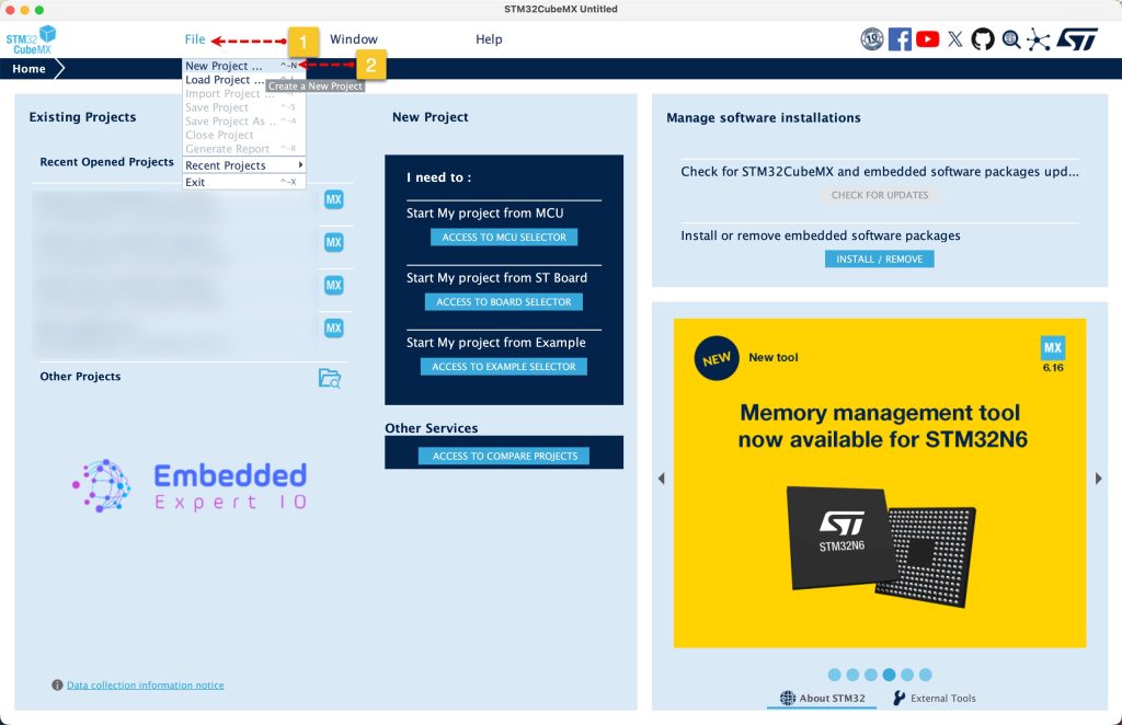
Open STM32CubeMX as start a new project as follows:
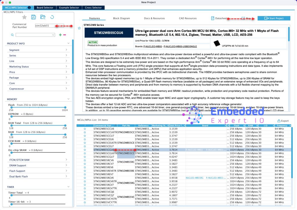
Search for your STM32 MCU, select the MCU and click on Start New Project as follows:
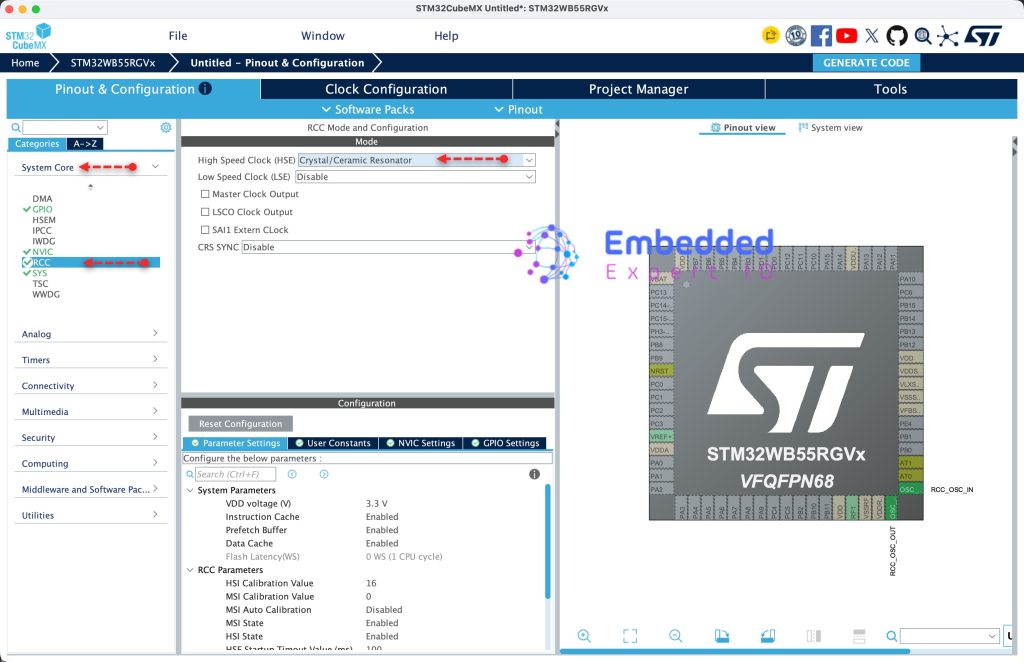
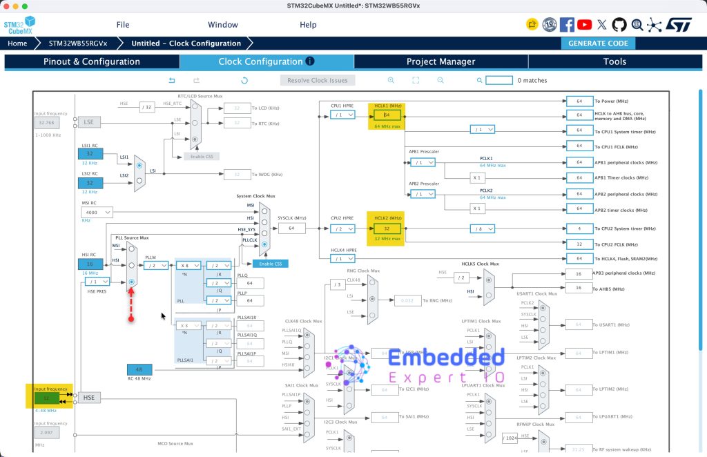
First, we need to configure the clock, since the board has 32MHz on board oscillator, we shall use.
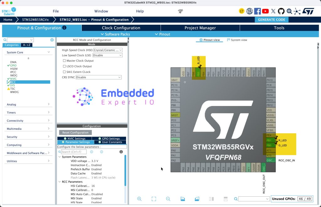
From System Core, select RCC and set HSE to Ceramic/Crystal oscillator as follows:
Next, from Clock Configuration, set the following:
- Input Frequency to 32MHz.
- PLL Source Mux to HSE.
- HCLK1 to 64MHz.
Next, we need to find which GPIO are connected to the LED, from the schematic of the board, we can find the following:
- PB5 is connected to Blue LED.
- PB1 is connected to
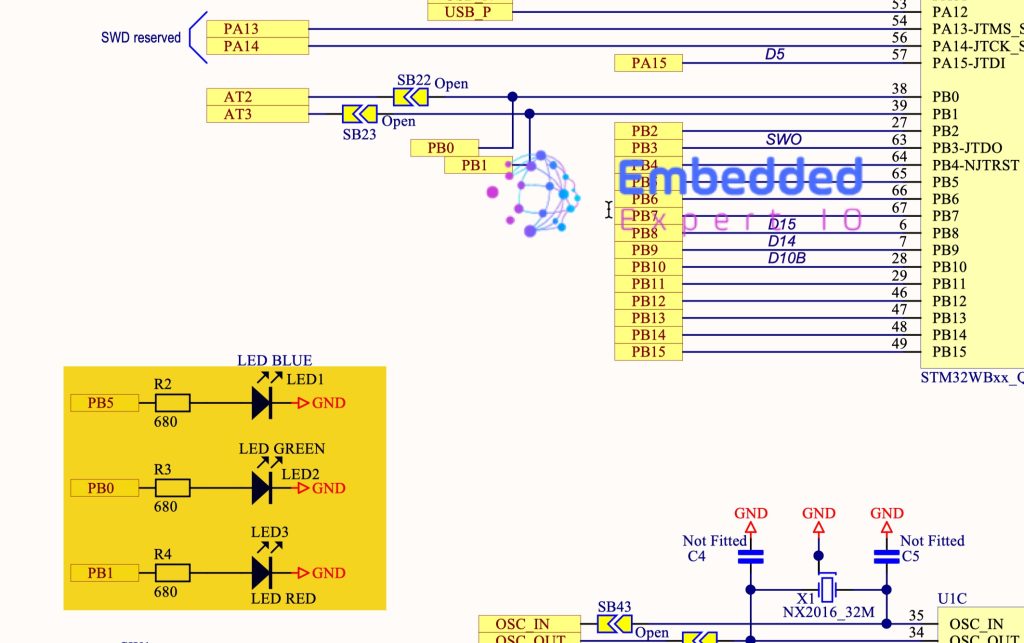
Hence, configure GPIO PB0, PB1 and PB5 as output and give them the following names:
- PB5 as B_LED.
- PB1 as R_LED.
- PB0 as G_LED.
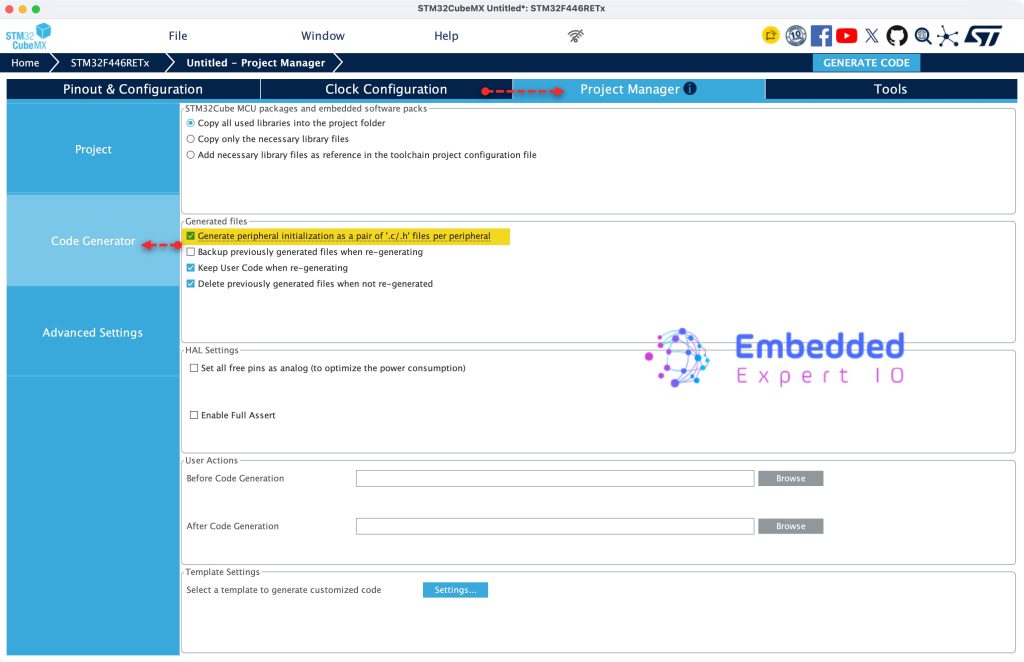
Next, from Code Generation in Project Manager, enable generation peripheral initialization as pair of .c/h per peripheral as follows:
Next, from Project, give the project as name, set the IDE/toolchain as STM32CubeIDE and click on Generate Code as follows:
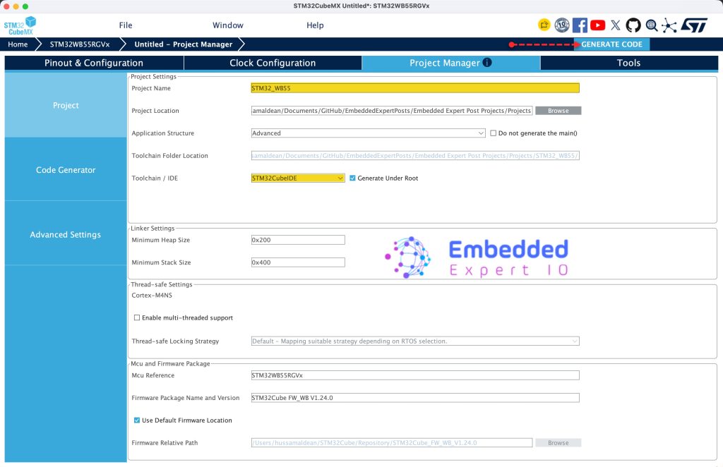
Thats all for STM32CubeMX.
3. Importing the Project to STM32CubeIDE:
Open STM32CubeIDE, select your workspace and click on Launch.
From the IDE, click File and select STM32 Project Create/Import as follows:
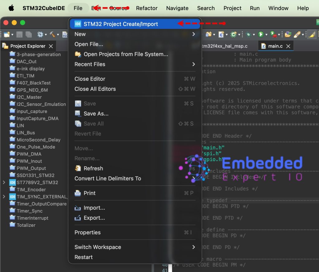
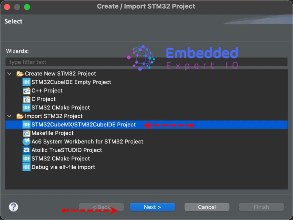
Next, from Import STM32 Project, select STM32CubeMX/STM32CubeIDE Project and click on Next as follows:
Next, select the folder that contains the .ioc file and click on Finish as follows:
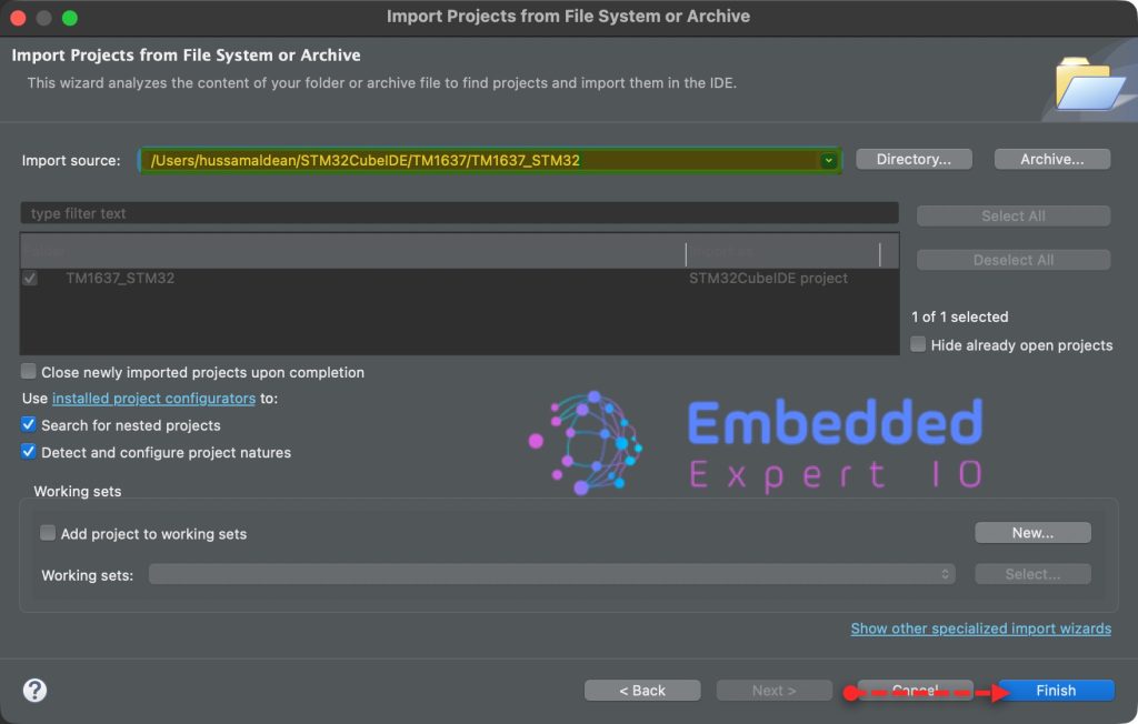
Note: Project name is for reference only.
4. Firmware Development:
Open main.c file.
In user code begin 3 in while 1 loop, we shall blink all LEDs at once.
HAL_GPIO_TogglePin(GPIOB, GPIO_PIN_0|GPIO_PIN_1|GPIO_PIN_5);
HAL_Delay(500);
Thats all for the firmware.
Save, build the project and run it as follows:

You may download the project from our github repository from here.
5. Results:
Once the flash process is completed, you shall see all three LEDs blinking as follows:
In next part, we shall configure the STM32WB55 to advertise.
Stay tuned.
Happy coding 😉

Add Comment