Expanding upon our single-channel DMA foundation, this guide scales the STM32F4’s ADC to simultaneously sample multiple analog channels. By enabling the ADC’s scan mode and linking it to the DMA controller via LL drivers, the system autonomously routes multi-channel conversion data directly into a structured memory array with zero CPU intervention.
In this guide, we shall cover the following:
- Introduction.
- STM32CubeMX configuration.
- Firmware development.
- Results.
1. Introduction:
As we scale up our embedded applications, monitoring a single analog channel is rarely sufficient. Real-world control systems—such as motor controllers, industrial sensor arrays, or battery management systems—demand the simultaneous monitoring of multiple analog inputs. For instance, a 3-phase motor controller must continuously and synchronously read multiple current sensors and temperature probes to maintain safe, closed-loop operation. Transitioning from a single-channel setup to a multi-channel acquisition on the STM32F4 introduces new hardware mechanics, primarily the ADC’s Scan Mode.
The Mechanics of Multi-Channel Acquisition: Scan Mode
When dealing with multiple channels, the ADC can no longer simply look at one pin. The STM32F4’s ADC features a multi-channel Sequencer, governed by Scan Mode. When Scan Mode is enabled, the ADC does not just perform a single conversion; it sweeps through a predefined list of channels—configured in the Sequence Registers (ADC_SQRx)—converting them one by one in a continuous sequence.
For example, if you configure the sequence to read Channel 1, Channel 2, and Channel 3, the ADC will convert Channel 1, immediately switch multiplexers to Channel 2, convert it, and finally switch to Channel 3. Crucially, because the ADC operates sequentially, the converted data for all these channels is pushed out through the exact same single Data Register (ADC_DR) at different points in time.
The Multi-Channel DMA Synergy
If you were to use interrupts for this multi-channel scan, you would face a severe architectural problem. Every single channel’s completion would fire an End-of-Conversion (EOC) interrupt. For a 3-channel sequence, that is three separate interrupt context switches per sweep, forcing the CPU to constantly rescue data from the single data register before it gets overwritten by the next channel’s conversion. At high frequencies, this will instantly overwhelm the Cortex-M4 core.
This is where the combination of DMA and Scan Mode becomes an absolute necessity. By linking the ADC to a DMA stream, we can enable the End of Regular Conversion (EOC) DMA request. As the ADC sweeps through the channels in Scan Mode, the DMA controller acts as a high-speed relay catcher. Every time a channel finishes converting, the DMA controller automatically pulls the data from the ADC_DR and places it into a memory array.
Because the data arrives sequentially (Channel 1’s data goes to buffer[0], Channel 2’s data goes to buffer[1], and Channel 3’s data goes to buffer[2]), the DMA seamlessly constructs a perfectly organized, multi-dimensional array of your analog environment in the background.
The LL Driver Advantage in Complex Routing
Configuring multi-channel ADC with DMA is one of the most complex routing tasks on the STM32F4. You must configure the ADC Sequence Registers (SQR1, SQR2, SQR3), manage the individual channel sampling times, and meticulously map the ADC’s DMA request to the correct DMA controller stream and channel.
Using the HAL library for this level of hardware routing often results in hidden state errors, obscure callback chains, and significant setup latency. By utilizing the LL Drivers, we retain absolute, transparent control over this complex silicon routing. We will manually define the sequence length, write the channel numbers directly into the sequence registers, and hardcode the DMA stream’s peripheral-to-memory configuration. This bare-metal approach ensures our multi-channel data pipeline remains incredibly lean, highly deterministic, and perfectly synchronized, providing a rock-solid foundation for any complex, multi-sensor embedded project.
In the following sections, we will dive into the exact LL register configurations required to enable Scan Mode, structure the ADC sequence, and configure the DMA to autonomously build our multi-channel memory buffer.
2. STM32CubeMX Configuration:
We shall continue from the previous guide from here.
First, before we configure any extra pins, we need to find which pins are connected to the ADC, since this guide uses STM32F446RE Nucleo-64, Arduino pins from A0 to A5 are ADC channels:
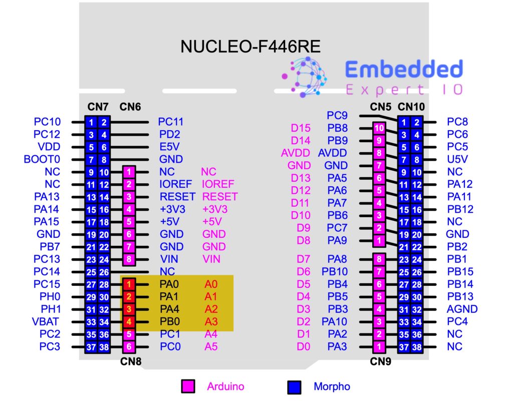
Since we shall use Arduino pins from A0 to A3 thats means we shall configure PA0, PA1, PA4 and PB0 as analog input.
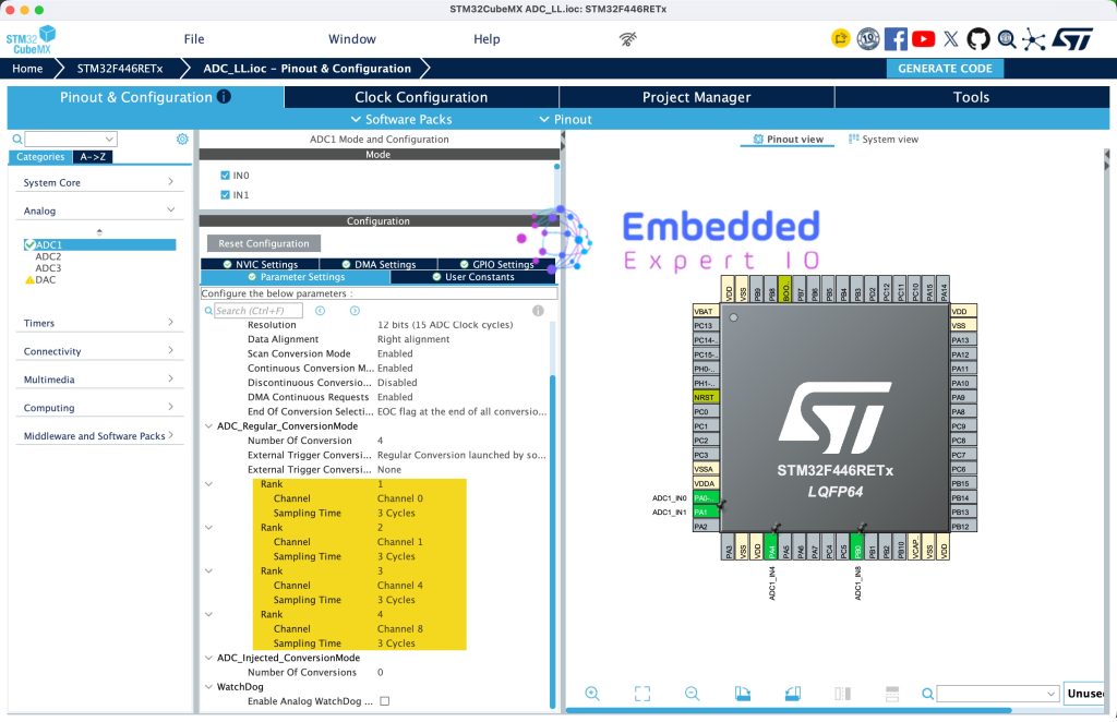
Hence, open the project .ioc file and configure the pins to ADC as follows:
- PA0 as ADC1_IN0
- PA1 as ADC1_IN1
- PA4 as ADC1_IN4
- PB0 as ADC1_IN8
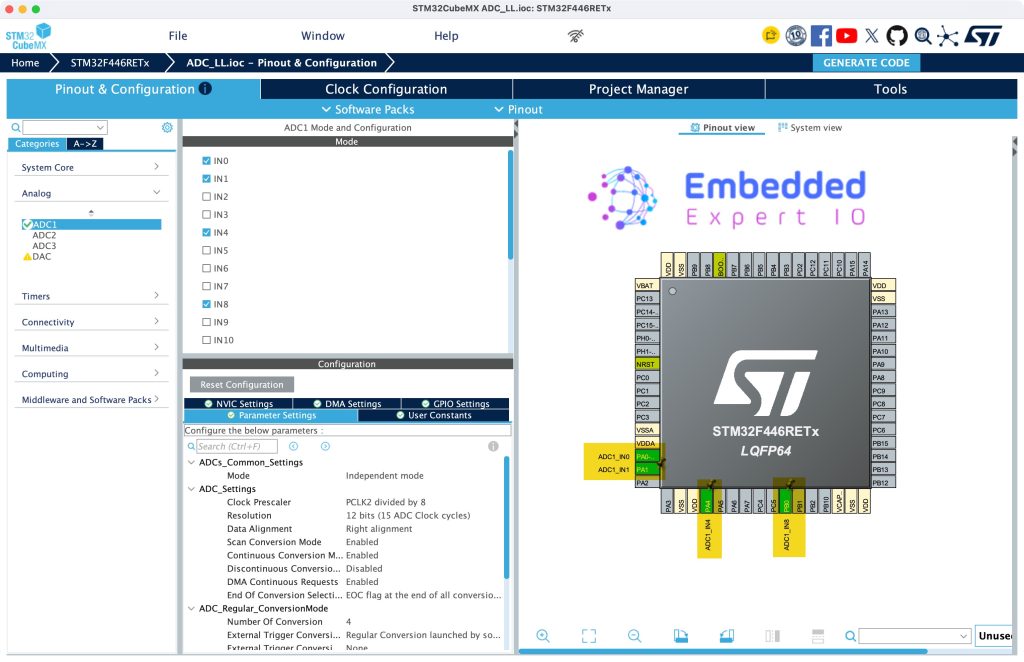
Next, from Parameters Settings:
- Set Scan Conversion Mode to Enable
- Set Number of Conversion to 4 or how many channels you enabled.
Next, from Rank, set the Rank as follows:
- Rank 1 to CH0
- Rank 2 to CH1
- Rank 3 to CH4
- Rank 4 to CH8
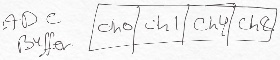
In short, it is how the ADC push the data and in which order, this means the ADC will convert CH0 then CH1 then CH2 and finally CH8 and go back to convert CH0. The DMA will store the data as follows:
Thats all for the STM32CubeMX configuration.
Click on Generate Code.
3. Firmware Development:
Open the project in STM32CubeIDE.
Open the adc.h header file
In user code begin Prototytpes, declare the following function:
void ADC_Start_DMA_MultiChannnel(uint16_t *adcBuff, uint16_t len);
This function shall start the ADC in DMA mode for multiple channels.
Thats all for the header file.
Open adc.c source file.
In user code begin 1,
Declare the function:
void ADC_Start_DMA_MultiChannnel(uint16_t *adcBuff, uint16_t len)
Within the function:
Disable the stream and make sure it is disabled:
LL_DMA_DisableStream(DMA2, LL_DMA_STREAM_0);
while (LL_DMA_IsEnabledStream(DMA2, LL_DMA_STREAM_0));
Next, set the peripheral address to ADC data register:
LL_DMA_SetPeriphAddress(DMA2, LL_DMA_STREAM_0, LL_ADC_DMA_GetRegAddr(ADC1, LL_ADC_DMA_REG_REGULAR_DATA));
Next, set the memory address which is passed by the user:
LL_DMA_SetMemoryAddress(DMA2, LL_DMA_STREAM_0, (uint32_t)adcBuff);
Set the length to the length passed by the user:
LL_DMA_SetDataLength(DMA2, LL_DMA_STREAM_0, len);
Next, enable the DMA stream:
LL_DMA_EnableStream(DMA2, LL_DMA_STREAM_0);
Finally, enable the ADC and start the conversion:
LL_ADC_Enable(ADC1);
LL_ADC_REG_StartConversionSWStart(ADC1);
Hence, the function as follows:
void ADC_Start_DMA_MultiChannnel(uint16_t *adcBuff, uint16_t len)
{
    LL_DMA_DisableStream(DMA2, LL_DMA_STREAM_0);
    while (LL_DMA_IsEnabledStream(DMA2, LL_DMA_STREAM_0));

    LL_DMA_SetPeriphAddress(DMA2, LL_DMA_STREAM_0, LL_ADC_DMA_GetRegAddr(ADC1, LL_ADC_DMA_REG_REGULAR_DATA));
    LL_DMA_SetMemoryAddress(DMA2, LL_DMA_STREAM_0, (uint32_t)adcBuff);
    LL_DMA_SetDataLength(DMA2, LL_DMA_STREAM_0, len);

    LL_DMA_EnableStream(DMA2, LL_DMA_STREAM_0);

    LL_ADC_Enable(ADC1);
    LL_ADC_REG_StartConversionSWStart(ADC1);
}
Next, open main.c
In user code begin PV, update the adc_value to be array of 4 as follows:
uint16_t adc_value[4];
In user code begin 2 in main function, start the multichannel adc as follows:
ADC_Start_DMA_MultiChannnel(adc_value,4);
Thats all for the guide.
Save, build the project and run it as follows:

You may download the project from our github repository from here.
4. Results:
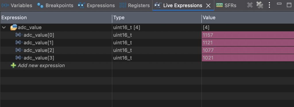
Open a debugging session, add adc_value to live expression, you should get something like this:
Thats all for this guide.
Next, we shall use timer to trigger the ADC conversion at fixed rate.
Stay tuned.
Happy coding 😉

Add Comment