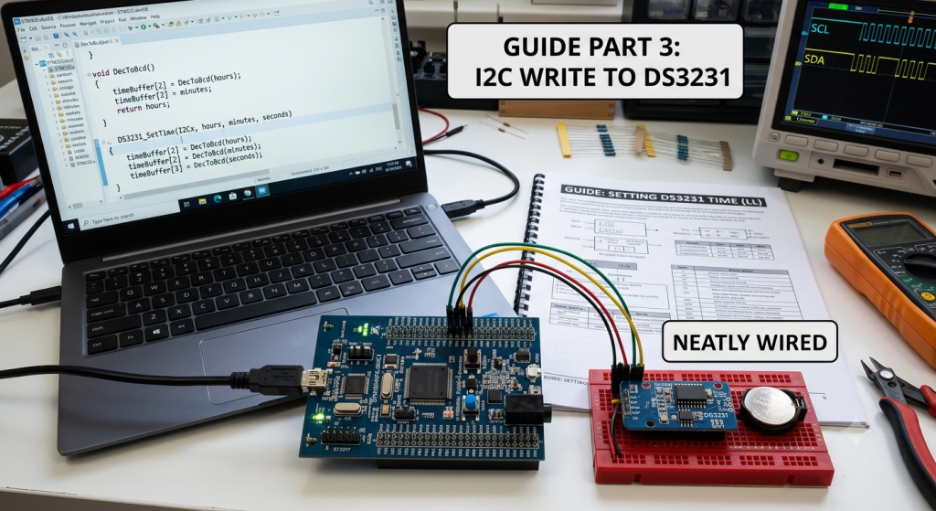
In this third installment of our STM32 Low-Layer (LL) I2C series, we shift from receiving data to actively configuring slave peripherals by updating the time registers on the DS3231 RTC. We will explore how to build a robust multi-byte write routine and manage Binary-Coded Decimal (BCD) conversions to accurately set the hours, minutes, and seconds.
In this guide, we shall cover the following:
- Introduction.
- Firmware Development.
- Results.
1. Introduction:
Communicating with Slave Devices: Register Writing via STM32 Low-Layer (LL) I2C APIs
In the preceding parts of this series, we explored the mechanics of scanning the I2C bus to discover connected hardware and established a low-level reception pipeline to retrieve data from slave devices. However, real-world embedded applications demand bidirectional communication. Configuring sensors, setting up control registers, writing configuration parameters, or initializing state variables require a robust, deterministic method for transmitting data from the microcontroller to any target peripheral on the bus.
In this third installment, we complete the foundational I2C communication loop by focusing on general register-level write operations. We will examine how to construct a multi-byte master-transmission sequence using STM32 Low-Layer (LL) drivers to reliably send configuration bytes and payload data to any I2C slave peripheral.
The Anatomy of an I2C Write Operation
Unlike an I2C memory read sequence—which requires a two-stage transaction using a Repeated START condition to switch hardware roles from master-transmitter to master-receiver—a standard register write operation is entirely unidirectional. The STM32 acts strictly as a master-transmitter, driving both the clock line (SCL) and data line (SDA) throughout the entire payload sequence.
The physical protocol sequence flows in a continuous, unbroken stream across the bus:
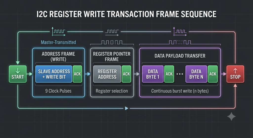
1. Initiating the Transaction
The process begins with the STM32 generating a START condition, pulling the SDA line low while SCL remains high to claim control of the bus. Following the START signal, the microcontroller transmits the target 7-bit peripheral address appended with a Write Bit (0) as the Least Significant Bit ($LSB = 0$). If the slave device is online and listening, it asserts an Acknowledge (ACK) signal by pulling the SDA line low during the ninth clock pulse.
2. Positioning the Register Pointer
Once the slave acknowledges its address, the master transmits the internal memory or register address where data needs to be written (for instance, 0x00, pointing to a control or configuration register). The slave peripheral stores this byte in its internal address pointer and sends another ACK. On most I2C peripherals, this internal pointer automatically increments after every subsequent byte transferred, enabling continuous burst writes to contiguous memory locations.
3. Transmitting the Payload & Closing the Bus
With the target register address locked in, the STM32 sequentially pumps the payload bytes across the data line—whether sending configuration flags, thresholds, or operational modes. The target slave acknowledges each individual byte as it is written to internal memory. To gracefully conclude the transaction, the master waits for the physical shift register to clear and then generates a STOP condition, releasing the bus lines back to their idle state.
Managing Multi-Byte and 16-Bit Register Addresses
Different I2C slave peripherals organize their internal register maps differently depending on memory capacity and design:
- 8-Bit Register Addressing: Common in standard sensors, IO expanders, and microcontrollers. The register address fits entirely into a single byte immediately following the slave address frame.
- 16-Bit Register Addressing: Common in larger external memory devices like EEPROMs (e.g., 24C32/24C64). The internal memory location requires two bytes (High Byte followed by Low Byte) before payload data can be clocked in.
Designing a general-purpose write routine means handling both single-byte and two-byte register addressing seamlessly before streaming the data payload.
Precision Hardware Control with STM32 Low-Layer (LL)
Writing to I2C registers using Low-Layer drivers gives you full visibility into the microcontroller’s underlying hardware state machine. While higher-level frameworks handle these timing checks internally, LL forces you to monitor specific status flags in the hardware registers at each phase of the write cycle:
SB(Start Bit Generated): Confirms that the start condition has been driven onto the bus.ADDR(Address Sent / Matched): Verifies that the slave device recognized its address and responded with an ACK.TXE(Transmit Data Register Empty): Signals that the internal data register (DR) is empty and ready to accept the next byte from CPU memory.BTF(Byte Transfer Finished): Ensures that not only has the data register been cleared, but the internal hardware shift register has completely finished clocking out the final bit on the physical SDA line before a STOP condition is asserted.
By taking direct charge of these flag checks, you eliminate driver overhead, create deterministic timing routines, and gain complete control over your microcontroller’s I2C hardware peripheral.
2. Firmware Development:
We shall continue from the previous guide from here.
Open i2c.h header file.
In user code exported function, declare the following function:
void I2C_Mem_Write(I2C_TypeDef *I2Cx,uint8_t slaveAddress, uint16_t regAddress,uint8_t regLen, uint8_t *data, uint16_t length);
I2C_TypeDef *I2Cx
- Type: Pointer to an I2C hardware peripheral instance (e.g.,
I2C1,I2C2). - Purpose: Directs the function to the specific peripheral base registers (
I2Cx->DR,I2Cx->CR1,I2Cx->SR1, etc.) driving the physical SCL and SDA lines on your MCU.
uint8_t slaveAddress
- Type: 7-bit peripheral address.
- Purpose: Identifies the target slave device on the bus (e.g.,
0x68for an RTC or0x50for an EEPROM). - Hardware Execution: The function left-shifts this address by 1 bit (
slaveAddress << 1) and clears bit 0 to signal a Write operation (LSB=0).
uint16_t regAddress
- Type: Internal target memory or register address inside the slave device.
- Purpose: Specifies where inside the slave device to start writing data.
- Hardware Execution: Transmitted across the bus immediately after the slave device acknowledges its base address.
uint8_t regLen
- Type: Size (in bytes) of the internal register address (
regAddress). - Purpose: Adapts the driver to different types of slave hardware:
1byte: For standard 8-bit register maps (sensors, IO expanders, RTCs).2bytes: For 16-bit memory addresses (such as higher-capacity EEPROMs, e.g., 24C32/24C64), where the address is sent as High Byte followed by Low Byte.
uint8_t *data
- Type: Pointer to a buffer in MCU RAM containing the payload bytes.
- Purpose: Holds the raw data bytes you wish to write (e.g., configuration bits, threshold values, or time data).
uint16_t length
- Type: Total number of bytes to write.
- Purpose: Controls the loop iteration count. Because most I2C slave devices auto-increment their internal register pointer after every byte write, passing a
length > 1executes a burst write across contiguous registers in a single transaction.
Thats all for the header file.
Next, open i2c.c source file.
For the write function, we shall implement the flow of the write as mentioned in the introduction and it has the following flow diagram:
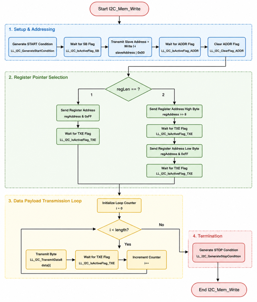
void I2C_Mem_Write(I2C_TypeDef *I2Cx,uint8_t slaveAddress, uint16_t regAddress,uint8_t regLen, uint8_t *data, uint16_t length)
{
    // Generate START condition
    LL_I2C_GenerateStartCondition(I2Cx);
    while(!LL_I2C_IsActiveFlag_SB(I2Cx));

    // Send device address with write bit
    LL_I2C_TransmitData8(I2Cx, (slaveAddress ) | 0x00);
    while(!LL_I2C_IsActiveFlag_ADDR(I2Cx));
    LL_I2C_ClearFlag_ADDR(I2Cx);

    if (regLen == 1)
      {
          LL_I2C_TransmitData8(I2Cx, regAddress & 0xFF);
          while(!LL_I2C_IsActiveFlag_TXE(I2Cx));
      }

      else if (regLen == 2)
      {
          // Send regAddress high byte
          LL_I2C_TransmitData8(I2Cx, (uint8_t)(regAddress >> 8));
          while(!LL_I2C_IsActiveFlag_TXE(I2Cx));

          // Send regAddress low byte
          LL_I2C_TransmitData8(I2Cx, (uint8_t)(regAddress & 0xFF));
          while(!LL_I2C_IsActiveFlag_TXE(I2Cx));
      }

    // Send all data bytes
    for(uint16_t i = 0; i < length; i++)
    {
        LL_I2C_TransmitData8(I2Cx, data[i]);
        while(!LL_I2C_IsActiveFlag_TXE(I2Cx));
    }

    // Generate STOP condition
    LL_I2C_GenerateStopCondition(I2Cx);


}
Thats all for the firmware.
Next, open main.c file.
In user code begin PV (Private Variables):
uint8_t RTCDataWrite[3]={0};This will contain the data to be written to the sd3231 rtc module
Also, include the stdlib for random number generator as follows:
#include "stdlib.h"
Next, in user code begin 0, declare a function that will allow us to convert the decimal to BCD as follows:
uint8_t DEC_to_BCD(uint8_t dec)
{
    // Dividing by 10 shifts the tens digit to the lower nibble.
    // Modulo 10 isolates the ones digit.
    return (uint8_t)((dec / 10) << 4) | (dec % 10);
}
In user code begin 3 in while 1 loop:
First, read the time registers as follows:
I2C_Mem_Read(I2C1,ds3231_addr,0x00,1,RTCData,3);
Next, if the reminder of the division by 5 for the seconds is 0:
if((bcdToDec(RTCData[0]) % 5) == 0)
Update the time register with random values for minutes and hours and set the seconds as 1 as follows:
RTCDataWrite[0]=DEC_to_BCD(1);
RTCDataWrite[1]=DEC_to_BCD(random()%10);
RTCDataWrite[2]=DEC_to_BCD(random()%10);
printf("New value set\r\n");
Next, write the new data to the module as follows:
printf("DS3231 register values:\r\n");

printf("Seconds=%d\r\n",bcdToDec(RTCData[0]));
printf("Minutes=%d\r\n",bcdToDec(RTCData[1]));
printf("Hours=%d\r\n",bcdToDec(RTCData[2]));

for (volatile int32_t i=0;i<1000000;i++)
{
  //DO Nothing
}
Thats all for the guide.
Save, build the project and run it as follows:

You may download the project file from here.
3. Results:
Open your serial terminal and you should something like this:
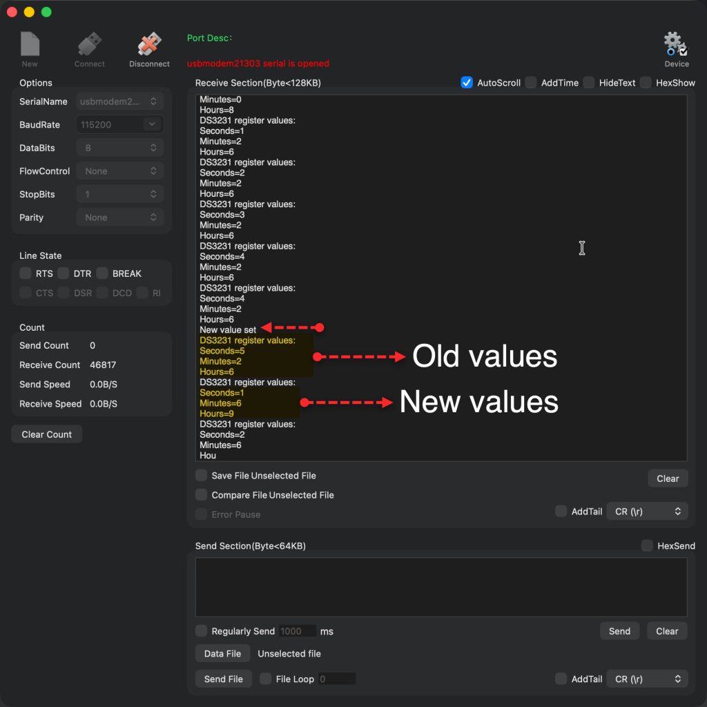
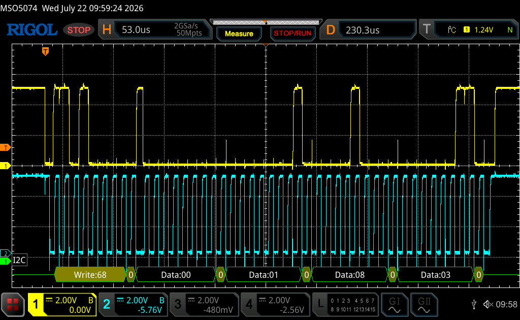
Here is the bus state during the writing:
Stay tuned.
Happy coding

Add Comment