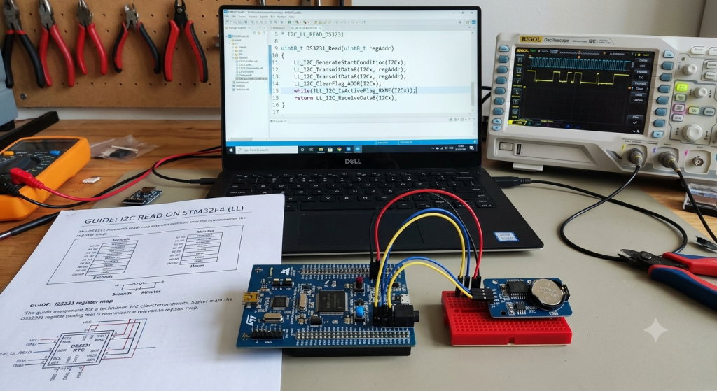
For the second part of our series, we transition from bus scanning to active data retrieval by interfacing with the highly accurate DS3231 Real-Time Clock (RTC). We will break down the essential register operations and timing requirements needed to implement a robust I2C read sequence using Low-Layer (LL) APIs, establishing a reliable foundation for all your future sensor integrations.
In this guide, we shall cover the following:
- Introduction.
- Firmware development.
- Results.
1. Introduction:
Mastering I2C Read Operations: Interfacing the DS3231 RTC via STM32 Low-Layer (LL) APIs
When developing firmware for resource-constrained embedded systems, moving away from high-level abstractions like the Hardware Abstraction Layer (HAL) is often the key to unlocking maximum hardware efficiency. While HAL drivers offer ease of use and rapid prototyping, they hide the register-level state transitions under layers of generic code, making it difficult to optimize for speed, memory footprint, or deterministic execution.
In this second installment of our STM32 I2C Low-Layer series, we move past basic bus scanning to tackle the fundamental mechanics of reading data from a real-world slave peripheral. To build this foundation, we will interface with the widely used DS3231 Real-Time Clock (RTC). Known for its temperature-compensated crystal oscillator and high accuracy, the DS3231 provides an ideal, highly predictable playground for mastering the intricate timing, repeated-start conditions, and precise status flag synchronization required by the physical I2C protocol.
The Anatomy of an I2C Read Operation
Reading data from a specific register inside an I2C peripheral is not a single, continuous operation. Instead, it is a two-step process that combines both a Write transaction (to set the target register pointer) and a Read transaction (to retrieve the actual data). This sequence is commonly executed using a Repeated START condition to prevent other master devices on the bus from interrupting the communication flow.
The physical sequence on the SDA and SCL lines flows as follows:
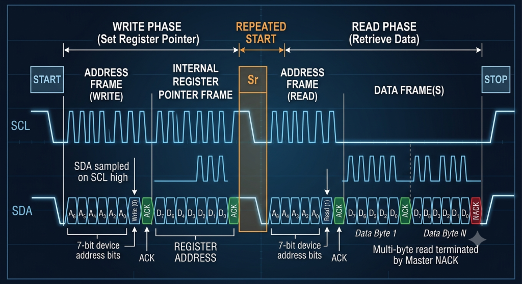
1. The Write Phase (Setting the Register Pointer)
Before you can read a value, you must tell the DS3231 which register you want to read. The STM32 acts as a master-transmitter:
- START Condition: The master pulls the SDA line low while SCL remains high to claim the bus.
- Device Address + Write Bit: The master transmits the 7-bit DS3231 address (
0x68) shifted left, with the LSB cleared to0(indicating a write command). - Register Address: Once the DS3231 acknowledges its address, the master transmits the specific register address (for example,
0x00to access the Seconds register or0x01for Minutes).
2. The Repeated START (SR) Condition
Rather than releasing the bus with a STOP condition—which would invite bus contention in multi-master environments—the master generates a Repeated START. This allows the master to immediately transition into receiver mode while maintaining exclusive control over the physical lines.
3. The Read Phase (Retrieving the Register Data)
Now, the STM32 acts as a master-receiver to fetch the data byte:
- Device Address + Read Bit: The master transmits the 7-bit DS3231 address (
0x68) shifted left, this time setting the LSB to1to signal a read transaction. - Data Byte Reception: The DS3231 takes control of the SDA line and clocks out the requested data byte.
- NACK and STOP Condition: For a single-byte read, the master must immediately reply with a No-Acknowledge (NACK) after receiving the byte. This signals to the DS3231 that the transfer is complete, preventing it from continuously clocking out subsequent registers. The master then terminates the transaction by driving a STOP condition onto the bus.
Why Use the Low-Layer (LL) Approach?
Implementing this multi-step read sequence using STM32 Low-Layer (LL) APIs forces you to directly interact with the hardware’s internal register flags.
Unlike the HAL equivalent (HAL_I2C_Mem_Read), which manages the entire transaction using an internal state machine behind a single function call, LL drivers require you to explicitly handle the hardware state transitions. You must check status registers for critical flags like:
SB(Start Bit): To verify that the start condition is actively on the line.ADDR(Address Sent): To confirm that the target device has detected its address and pulled the bus line low (ACK).TXE(Transmit Data Register Empty): To ensure the hardware is ready for the next outgoing byte.RXNE(Receive Data Register Not Empty): To wait for the incoming data byte to safely land in the input buffer before reading it.
While this direct register manipulation demands a deeper understanding of the microcontroller’s hardware manual, it rewards you with a dramatically smaller memory footprint, lightning-fast execution, and the ability to write robust, custom error-handling loops tailored specifically to your hardware requirements. In the following sections of this guide, we will translate this hardware-level flow chart into highly optimized C-code using STM32 LL functions.
2. Firmware Development:
We shall continue from the previous guide from here.
Open i2c.h header file.
In user code exported function, declare the following function:
void I2C_Mem_Read(I2C_TypeDef *I2Cx,uint8_t slaveAddress, uint16_t regAddress, uint8_t regLen, uint8_t *data, uint16_t length);
I2C_TypeDef *I2Cx
- Description: The pointer to the specific hardware I2C peripheral instance on the STM32.
- Examples:
I2C1,I2C2, orI2C3. - Hardware Role: This dictates which physical pins (SCL/SDA) and internal registers (like
I2C_DR,I2C_CR1,I2C_SR1) the function will manipulate under the hood.
uint8_t slaveAddress
- Description: The 7-bit physical address of the target slave peripheral on the I2C bus.
- Example:
0x68for the DS3231 RTC. - Hardware Role: Inside your code, this address will be left-shifted by 1 bit (
slaveAddress << 1) to make room for the Read/Write bit in the least significant position before being written to the data register (DR).
uint16_t regAddress
- Description: The internal memory or register address inside the slave device where you want to start reading.
- Example:
0x00to target the “Seconds” register on the DS3231, or0x0010to target a specific memory cell in an external EEPROM. - Hardware Role: This value is sent during the initial “Write Phase” to position the slave’s internal register pointer before the repeated start occurs.
uint8_t regLen
- Description: The size (in bytes) of the internal register/memory address (
regAddress). - Values: Typically set to:
1(for standard 8-bit registers like the DS3231 or small EEPROMs).2(for larger memory devices like 24C32/24C64 EEPROMs that require a 16-bit internal address).
- Hardware Role: Tells your transmission loop whether to transmit the register address as a single 8-bit byte or split it into two 8-bit transfers (MSB then LSB) during the phase before the repeated start.
uint8_t *data
- Description: A pointer to the memory buffer in your STM32 RAM where the incoming bytes read from the slave will be stored.
- Hardware Role: As each byte is received by the I2C peripheral, the
RXNE(Receive Not Empty) flag will set. Your code will read this byte from the data register (I2Cx->DR) and store it sequentially in this array.
uint16_t length
- Description: The total number of sequential bytes you want to read from the slave device during this single transaction.
- Hardware Role: Tells your driver’s reception loop when to stop. This is critical for controlling the bus handshake: the STM32 master must automatically send an ACK after every received byte except for the final byte, where it must generate a NACK and a STOP condition to gracefully end the transmission.
Thats all for the header file.
Next, open i2c.c source file.
In user code begin 1, we shall implement the readmem function.
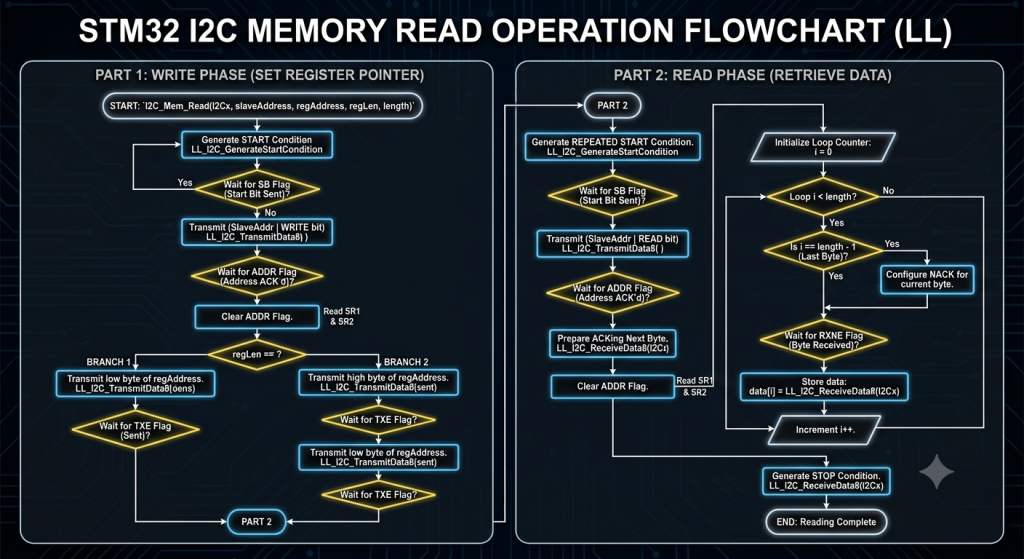
For the readmem function, we shall implement the flow of the read as mentioned in the introduction and it has the following flow diagram:
void I2C_Mem_Read(I2C_TypeDef *I2Cx,uint8_t slaveAddress, uint16_t regAddress, uint8_t regLen, uint8_t *data, uint16_t length)
{
    // Write phase: Send register address
    LL_I2C_GenerateStartCondition(I2Cx);

    while(!LL_I2C_IsActiveFlag_SB(I2Cx));

    LL_I2C_TransmitData8(I2Cx, (slaveAddress) | 0x00);

    while(!LL_I2C_IsActiveFlag_ADDR(I2Cx));

    LL_I2C_ClearFlag_ADDR(I2Cx);

    if (regLen == 1)
    {
        LL_I2C_TransmitData8(I2Cx, regAddress & 0xFF);
        while(!LL_I2C_IsActiveFlag_TXE(I2Cx));
    }

    else if (regLen == 2)
    {
        // Send regAddress high byte
        LL_I2C_TransmitData8(I2Cx, (uint8_t)(regAddress >> 8));
        while(!LL_I2C_IsActiveFlag_TXE(I2Cx));

        // Send regAddress low byte
        LL_I2C_TransmitData8(I2Cx, (uint8_t)(regAddress & 0xFF));
        while(!LL_I2C_IsActiveFlag_TXE(I2Cx));
    }


    // Read phase: Get data bytes
    LL_I2C_GenerateStartCondition(I2Cx);

    while(!LL_I2C_IsActiveFlag_SB(I2Cx));

    LL_I2C_TransmitData8(I2Cx, (slaveAddress) | 0x01);

    while(!LL_I2C_IsActiveFlag_ADDR(I2Cx));

    LL_I2C_AcknowledgeNextData(I2Cx, LL_I2C_ACK);

    LL_I2C_ClearFlag_ADDR(I2Cx);


    // Read all bytes
    for(uint16_t i = 0; i < length; i++)
    {
        if(i == length - 1)
        {
            LL_I2C_AcknowledgeNextData(I2Cx, LL_I2C_NACK);  // If last byte, Send NACK
        }

        while(!LL_I2C_IsActiveFlag_RXNE(I2Cx));

        data[i] = LL_I2C_ReceiveData8(I2Cx);
    }

    LL_I2C_GenerateStopCondition(I2Cx);
}
Thats all for the firmware.
Next, open main.c file.
In user code begin PV (Private Variables):
Declare the slave address and shift the address to left by 1 as follows:
#define ds3231_addr 0x68<<1
Next, declare an array to hold the read rtc registers which they are three for seconds, minutes and hours as follows:
uint8_t RTCData[3]={0};Next, in user code begin 0, declare the following function, which will convert the BCD to readable format for human as follows:
uint8_t bcdToDec(uint8_t bcd) {
    return (bcd & 0x0F) + ((bcd >> 4) * 10);
}
Next, in while 1 loop:
Read the time register by starting with register 0x00 which is the second register followed automatically by minutes and hours for register number 0x01 and 0x02 respectively:
I2C_Mem_Read(I2C1,ds3231_addr,0x00,1,RTCData,3);
Next, print the register values as follows:
printf("DS3231 register values:\r\n");

printf("Seconds=%d\r\n",bcdToDec(RTCData[0]));
printf("Minutes=%d\r\n",bcdToDec(RTCData[1]));
printf("Hours=%d\r\n",bcdToDec(RTCData[2]));
Thats all for the guide.
Save, build the project and run it as follows:

You may download the project file from here.
3. Results:
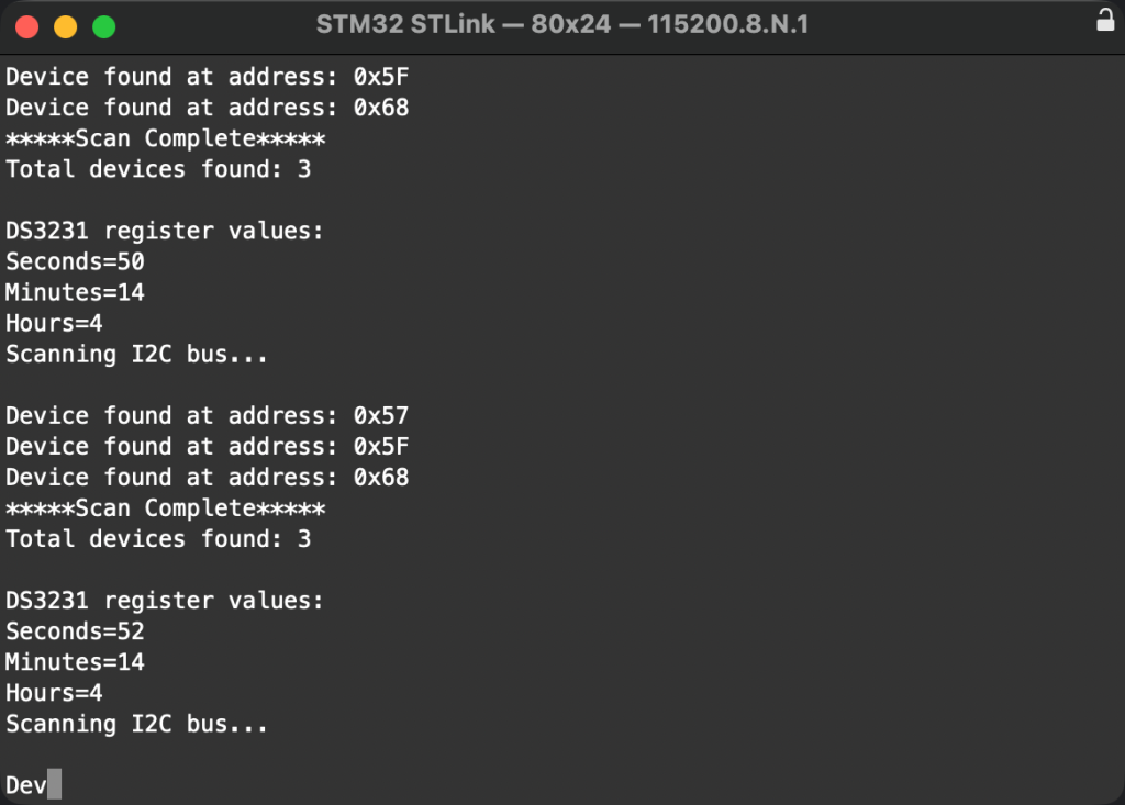
Open your serial terminal and you should something like this:
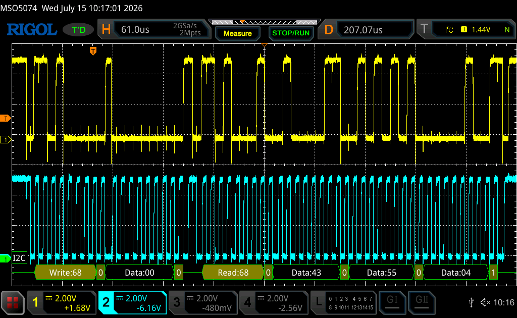
Here is a scope for the bus:
Next part, we shall write then read from i2c slave device.
Stay tuned.
Happy coding 😉

Add Comment