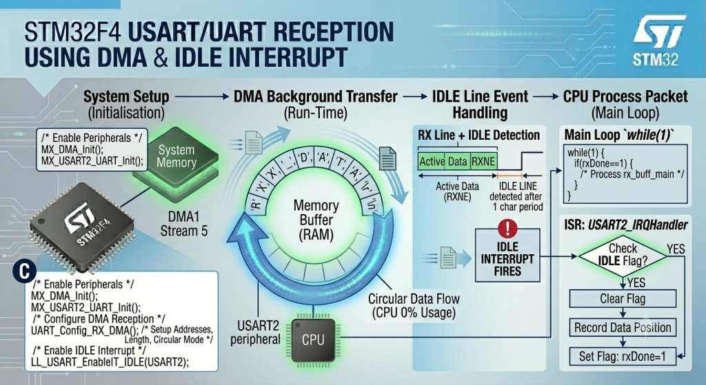
Eliminate the CPU overhead of processing individual incoming characters by offloading variable-length UART reception entirely to the DMA controller. By pairing a circular or linear DMA stream with the UART hardware’s IDLE line interrupt, you can seamlessly buffer unpredictable incoming data frames directly into RAM, freeing the processor to focus on high-level application logic until a complete packet is ready for parsing.
In this guide, we shall cover the following:
- Introduction.
- STM32CubeMX configuration.
- Firmware development.
- Results.
1. Introduction:
While utilizing the RXNE (Read Data Register Not Empty) interrupt prevents the CPU from getting stuck in blocking polling loops, high-speed data streams can still overwhelm your application. At high baud rates, a dense influx of data forces the processor to constantly execute context switches—tripping an interrupt, saving registers to the stack, reading a single byte, and returning—dozens of thousands of times per second. This processing tax drastically diminishes the CPU cycles available for execution of your core application logic.
The ultimate architecture for high-performance serial communication combines Direct Memory Access (DMA) with IDLE Line Detection.
By assigning a dedicated DMA stream (such as DMA1, Stream 5, Channel 4 for USART2 RX on the STM32F4) to operate in circular or continuous mode, incoming bytes bypass the CPU entirely. The UART hardware automatically signals the DMA controller the microsecond a byte enters its shift register. The DMA controller immediately captures that byte and streams it directly into a designated RAM buffer without a single line of code being executed by the processor.
The true power of this setup comes from pairing it with the IDLE line interrupt. Instead of waking up the CPU for every character, the processor remains at 0% utilization during the active transfer. The CPU is only interrupted once: when the transmitting device stops sending data and the RX line rests at logic high for one frame period. This triggers a single IDLEinterrupt, alerting your application that a complete, variable-length packet is sitting in memory and is ready for immediate processing.
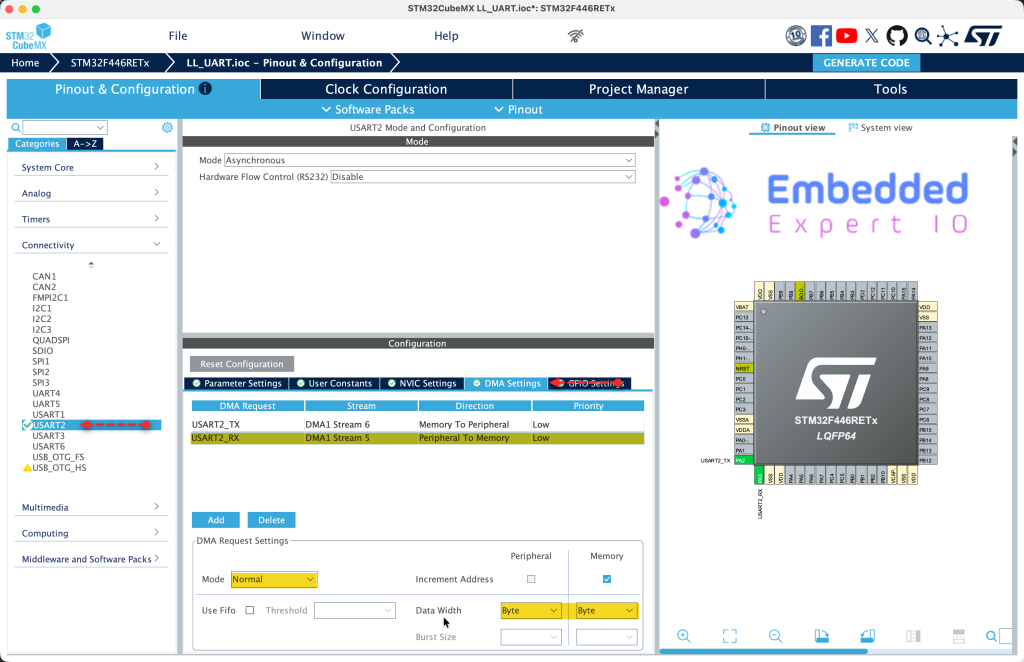
2. STM32CubeMX Configuration:
We shall continue from the previous guide from here.
Open project’s .ioc file in STM32CubeMX.
From USART2 tab, select DMA setting and add new DMA for USART2_RX as follows:
Next, from System Core, NVIC, code generation, disable code generation of DMA1_Stream5_IRQ_Handler and generate the code as follows
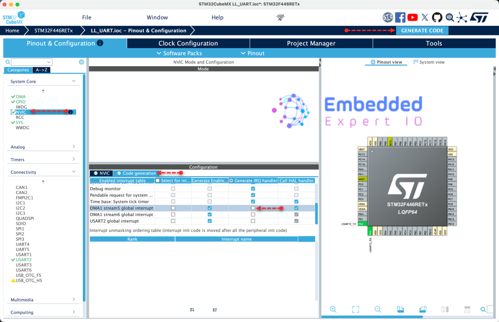
Thats all for the STM32CubeMX configuration.
3. Firmware Development:
Open your project in STM32CubeIDE.
In user code begin PV, declare this extra flag:
uint8_t iDMARX=0;
This will allow us to determine when IDLE line is triggered if the reception in interrupt mode or DMA
Next, for DMA1_Stream5 interrupt handler:
void DMA1_Stream5_IRQHandler(void)
{
	if (LL_DMA_IsActiveFlag_TC5(DMA1))
	{
		LL_DMA_ClearFlag_TC5(DMA1);
		LL_DMA_DisableStream(DMA1, LL_DMA_STREAM_5);
		ReceivedLen=RXBuffSize;


	}
}
Once the DMA received all the characters defined by RXBuffSize, TC will be triggered.
Once it is triggered, clear TC flag, disable the stream and set the received length to the buffer size.
Next, modify the IDLE interrupt within USART2_IRQ_Handler to have the following:
if(LL_USART_IsActiveFlag_IDLE(USART2))
{
  LL_USART_ClearFlag_IDLE(USART2);
  if(iDMARX==0)
  {
    ReceivedLen=rx_index;
    rx_index=0;
    rxDone=1;
  }

  if(iDMARX==1)
  {
    /* Calculate bytes received */
    ReceivedLen=RXBuffSize-LL_DMA_GetDataLength(DMA1, LL_DMA_STREAM_5);

    /*Clear IDLE flag*/
    LL_USART_ClearFlag_IDLE(USART2);

    /* Stop DMA to preserve received data */
    LL_DMA_DisableStream(DMA1, LL_DMA_STREAM_5);

    /* Clear any pending DMA flags */
    LL_DMA_ClearFlag_TC5(DMA1);

    rxDone = 1;
  }
}
This will allow the firmware to determine the received length in both cases, DMA or interrupt mode.
Next, declare the following function:
void UART_Receive_DMA_IDLE(uint8_t *ch, uint16_t len)
This function shall allow the user to receive data either for the length (100 characters for example) or until IDLE line is detected.
Within the function:
rxDone = 0;
ReceivedLen = 0;
iDMARX=1;

LL_DMA_DisableStream(DMA1, LL_DMA_STREAM_5);

LL_DMA_ClearFlag_TC5(DMA1);
LL_DMA_ClearFlag_HT5(DMA1);
LL_DMA_ClearFlag_TE5(DMA1);

LL_DMA_EnableIT_TC(DMA1, LL_DMA_STREAM_5);   // Enable Transfer Complete Interrupt

LL_USART_ClearFlag_IDLE(USART2);

LL_USART_EnableIT_IDLE(USART2);

LL_USART_EnableDMAReq_RX(USART2);  // Enable USART RX via DMA

LL_DMA_SetMemoryAddress(DMA1, LL_DMA_STREAM_5, (uint32_t)ch);
LL_DMA_SetPeriphAddress(DMA1, LL_DMA_STREAM_5, LL_USART_DMA_GetRegAddr(USART2));
LL_DMA_SetDataLength(DMA1, LL_DMA_STREAM_5, len);

LL_DMA_EnableStream(DMA1, LL_DMA_STREAM_5);
1. Reset Status Flags
rxDone = 0;
ReceivedLen = 0;
iDMARX = 1;
- rxDone = 0: Clear the reception complete flag so the main loop knows no new data has arrived yet
- ReceivedLen = 0: Reset the received byte counter to zero
- iDMARX = 1: Set a flag indicating DMA mode is active (used in the ISR to know that DMA, not interrupt-based RX, is handling reception)
2. Disable DMA Stream Before Configuration
LL_DMA_DisableStream(DMA1, LL_DMA_STREAM_5);
- Purpose: DMA stream must be disabled before you can modify its configuration registers
- DMA1: The DMA controller being used
- LL_DMA_STREAM_5: Stream 5 which is connected to USART2 RX
- Effect: Stops any ongoing DMA transfer if one was in progress
3. Clear All Pending DMA Flags
LL_DMA_ClearFlag_TC5(DMA1);
LL_DMA_ClearFlag_HT5(DMA1);
LL_DMA_ClearFlag_TE5(DMA1);
- TC5 (Transfer Complete): Clears flag that indicates DMA finished transferring all requested data (buffer full)
- HT5 (Half Transfer): Clears flag that indicates DMA has transferred half the buffer
- TE5 (Transfer Error): Clears any error flags from previous transfers
- Why: Prevents false triggers from previous operations
4. Enable DMA Transfer Complete Interrupt
LL_DMA_EnableIT_TC(DMA1, LL_DMA_STREAM_5);
- Purpose: Enable interrupt that fires when the DMA buffer becomes completely full
- Effect: If no IDLE line is detected before buffer fills up, this interrupt handles it
- Result:
DMA1_Stream5_IRQHandlerwill execute when buffer is full
5. Clear USART IDLE Flag
LL_USART_ClearFlag_IDLE(USART2);
- Purpose: Clear any previously pending IDLE line detection flag
- Why: The flag might be set from previous operations or during initialization
- How: Reads the USART status register followed by the data register to clear the IDLE flag
6. Enable USART IDLE Line Interrupt
LL_USART_EnableIT_IDLE(USART2);
- Purpose: Enable the interrupt that triggers when the RX line has been idle for one character period
- Meaning: When sender stops transmitting (end of message), this interrupt fires
- Effect: The IDLE check in
USART2_IRQHandlerwill now work
7. Enable USART DMA Request for RX
LL_USART_EnableDMAReq_RX(USART2);
- Purpose: Tell the USART peripheral to use DMA for receiving data instead of generating RXNE interrupts
- Effect: Every time a byte arrives, USART automatically triggers DMA to move it from the USART data register to memory
- Result: No CPU involvement needed for individual byte transfers
8. Configure DMA Source and Destination
LL_DMA_SetMemoryAddress(DMA1, LL_DMA_STREAM_5, (uint32_t)ch);
LL_DMA_SetPeriphAddress(DMA1, LL_DMA_STREAM_5, LL_USART_DMA_GetRegAddr(USART2));
LL_DMA_SetDataLength(DMA1, LL_DMA_STREAM_5, len);
- Memory Address: Where received data will be stored (your buffer
ch) - Peripheral Address: Where data comes from (USART2 data register)
- Data Length: Maximum number of bytes to transfer before stopping (your buffer size)
- Direction: Automatically moves data from USART to memory when each byte arrives
9. Enable DMA Stream
LL_DMA_EnableStream(DMA1, LL_DMA_STREAM_5);
- Purpose: Start the DMA engine
- Effect: DMA is now ready and waiting for USART to request transfers
- What happens next: When a byte arrives at USART, USART requests DMA, DMA moves the byte to memory, increments memory address, decrements remaining count
Flow After This Function:
- Byte arrives at USART → USART requests DMA
- DMA transfers byte to your buffer, increments address, decrements counter
- Repeat for each incoming byte
- If buffer fills →
DMA1_Stream5_IRQHandlerfires, setsReceivedLen = buffer size - If line goes idle →
USART2_IRQHandlerfires, stops DMA, calculatesReceivedLen = buffer size - remaining DMA count - Either way →
rxDoneflag is set to 1 - Main loop detects
rxDone == 1, processes the data, then calls this function again to restart
The key advantage: CPU does nothing during reception, only processes data when a complete message arrives (detected by IDLE line) or buffer is full.
Next, in while 1 loop:
if(rxDone==0)
{
  UART_Receive_DMA_IDLE((uint8_t*)uart_buff_rx,RXBuffSize);

  while(rxDone==0);
  rxDone=0;
  UART_Send_String(uart_buff_rx,ReceivedLen);

}
Code Explanation for UART DMA IDLE Reception Guide
Main Loop Code:
if(rxDone == 0)
{
    UART_Receive_DMA_IDLE((uint8_t*)uart_buff_rx, RXBuffSize);

    while(rxDone == 0);
    rxDone = 0;
    UART_Send_String(uart_buff_rx, ReceivedLen);
}
if(rxDone == 0)
- Checks if no reception has been completed yet
rxDoneis a global flag shared between main loop and interrupt handlers- Initially
rxDone = 0means “no data received” - This condition will be true at startup, entering the block to start reception
UART_Receive_DMA_IDLE((uint8_t*)uart_buff_rx, RXBuffSize);
- Calls the function that configures and starts DMA reception
- Parameters:
(uint8_t*)uart_buff_rx: Casts the character buffer to uint8_t pointer, telling DMA where to store incoming bytesRXBuffSize: Maximum number of bytes to receive (100 in this case)- This function:
- Disables any previous DMA transfer on Stream 5
- Clears old DMA flags
- Configures DMA to move data from USART2 data register to
uart_buff_rx - Enables IDLE line detection interrupt
- Starts the DMA stream
- After this call, DMA is actively waiting for incoming UART data
while(rxDone == 0);
- Blocking wait: The CPU stays here doing nothing until
rxDonebecomes 1 - This is a polling loop – it continuously checks the flag
- The flag will be set to 1 in either:
USART2_IRQHandlerwhen IDLE line is detected (end of message)DMA1_Stream5_IRQHandlerwhen buffer is completely full- During this wait, interrupts still fire and handle the actual data reception
- The semicolon means “do nothing while waiting”
rxDone = 0;
- Once the while loop exits (rxDone became 1), immediately clear the flag
- Prepares for next reception cycle
- Must be cleared before processing to avoid missing the next completion
UART_Send_String(uart_buff_rx, ReceivedLen);
- Processes the received data by echoing it back
uart_buff_rx: Contains the bytes that were received via DMAReceivedLen: Set by the ISR, tells exactly how many bytes were receivedUART_Send_Stringis a blocking function that transmits each byte and waits for completion
Complete Flow:
- First iteration:
rxDoneis 0, so code enters the if block - DMA is configured and started to receive into
uart_buff_rx - CPU blocks at
while(rxDone == 0)waiting for data - When data arrives, DMA automatically moves it from USART to buffer
- When line goes idle or buffer fills, ISR sets
rxDone = 1andReceivedLen - While loop exits,
rxDoneis cleared to 0 - Received data is echoed back via
UART_Send_String - Loop repeats:
rxDoneis 0 again, so DMA is reconfigured and started again
Thats all for the firmware.
Save, build and run the project as follows:

You may download the code from here.
4. Results:
Open your favourite terminal application, set the baudrate to 115200 and send any characters you want and you should get the following:
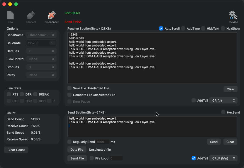
Now, your driver is ready for your application.
Next part, we shall user circular mode to handle the data professionally.
Stay tuned.
Happy coding 😉
Add Comment