
The INA219 is an I2C-based power monitoring module designed to measure high-side DC voltage, current, and power in real time. Interfacing this sensor with an STM32 microcontroller enables precise power tracking using standard HAL I2C drivers for embedded applications.
In this guide, we shall cover the following:
- Introduction.
- STM32CubeMX setup.
- Importing the project to STM32CubeIDE.
- Hardware setup.
- Firmware development.
- Results.
1. Introduction:
In modern embedded systems design, efficient energy management, system health monitoring, and precise power diagnostics are critical requirements. Whether developing battery-powered Internet of Things (IoT) nodes, robotics platforms, automated test fixtures, or solar-driven electronics, having granular visibility into voltage, current draw, and total power consumption is essential. Measuring electrical parameters allows microcontrollers to enforce dynamic thermal regulation, protect sensitive circuits from overcurrent events, log energy usage over extended periods, and make intelligent decisions based on remaining power reserves. To achieve accurate measurements without introducing significant circuit disruption or consuming vast computational overhead, dedicated hardware current and power monitor ICs are employed.
Among the various power monitoring solutions available on the market, the Texas Instruments INA219 stands out as a versatile, highly integrated, digital current and power sensor. Designed around a bi-directional current/power monitor architecture, the INA219 utilizes an onboard or external shunt resistor to measure current, bus voltage, and total power output simultaneously. Unlike basic operational amplifier current-sense circuits that output an analog voltage requiring heavy ADC sampling and signal conditioning, the INA219 performs internal signal processing and mathematical conversion using a 12-bit Delta-Sigma ADC. It then exposes these processed readings over a standard two-wire I2C(Inter-Integrated Circuit) bus interface, delivering high-precision readings while isolating the Host CPU from intensive math and sampling tasks.
Integrating the INA219 with an STM32 microcontroller creates a robust, industry-ready combination for high-performance DC power telemetry. The STM32 architecture—powered by ARM Cortex-M cores—offers rich peripheral sets, flexible Direct Memory Access (DMA) engines, and hardware I2C modules running alongside the STM32Cube Hardware Abstraction Layer (HAL). When combined with the INA219, an STM32-based controller can effortlessly poll current and voltage metrics in the background while running complex control loops, user interfaces, or wireless communication stacks.
To fully understand and leverage this sensor in an STM32 environment, it is useful to dive into the core working principles, key specs, and advantages of the INA219 module:
- High-Side Sensing Architecture: The INA219 measures current on the high side—between the power source and the load—rather than the low side. High-side sensing ensures that the system ground line remains uninterrupted, preventing common-mode ground loop noise and ensuring safety across sensitive sub-circuits.
- Wide Voltage Range: It natively handles common-mode bus voltages ranging from 0V up to +26V DC, making it ideal for standard industrial 12V and 24V systems, 3.3V/5V microcontroller logic rails, or 1S to 6S Lithium-ion battery packs.
- Flexible Precision & Calibration: The device uses aprogrammable calibration register to auto-calculate current in amperes and power in watts directly within the chip’s memory, offloading mathematical unit conversion from the STM32 firmware.
- Standardized Digital Communications: Communicating over standard I2C with configurable address pins, up to 16 INA219 modules can coexist on a single bus, enabling multi-channel power monitoring systems controlled by a single STM32 host.
By understanding the foundational roles of both the INA219 sensor and the STM32 microcontroller platform, you can effectively integrate real-time power analytics into your custom hardware designs.
2. STM32CubeMX Setup:
Open STM32CubeMX as start a new project as follows:

Search for your STM32 MCU, select the MCU and click on Start New Project as follows:
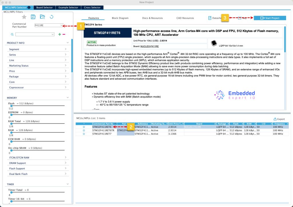
Next, set PB8 and PB9 for I2C, configure the I2C as follows:

Next, from Project Manager, Code Generation, set generation the initialization of peripheral as .c/.h for each peripheral as follows:

Next, from Project, from Project Manager, set the toolchain/IDE to STM32CubeIDE, give the project a name and click on Generate Code as follows:

Thats all of the STM32CubeMX configuration.
3. Importing the Project to STM32CubeIDE:
Open STM32CubeIDE, select your workspace and click on Launch.
From the IDE, click File and select STM32 Project Create/Import as follows:
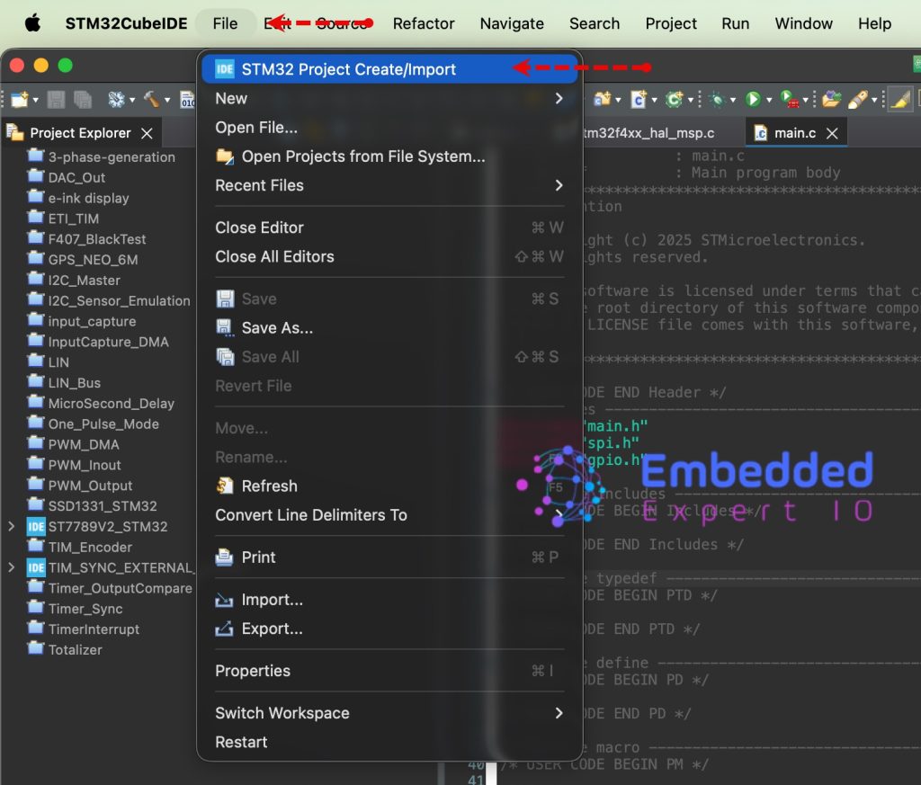
Next, from Import STM32 Project, select STM32CubeMX/STM32CubeIDE Project and click on Next as follows:
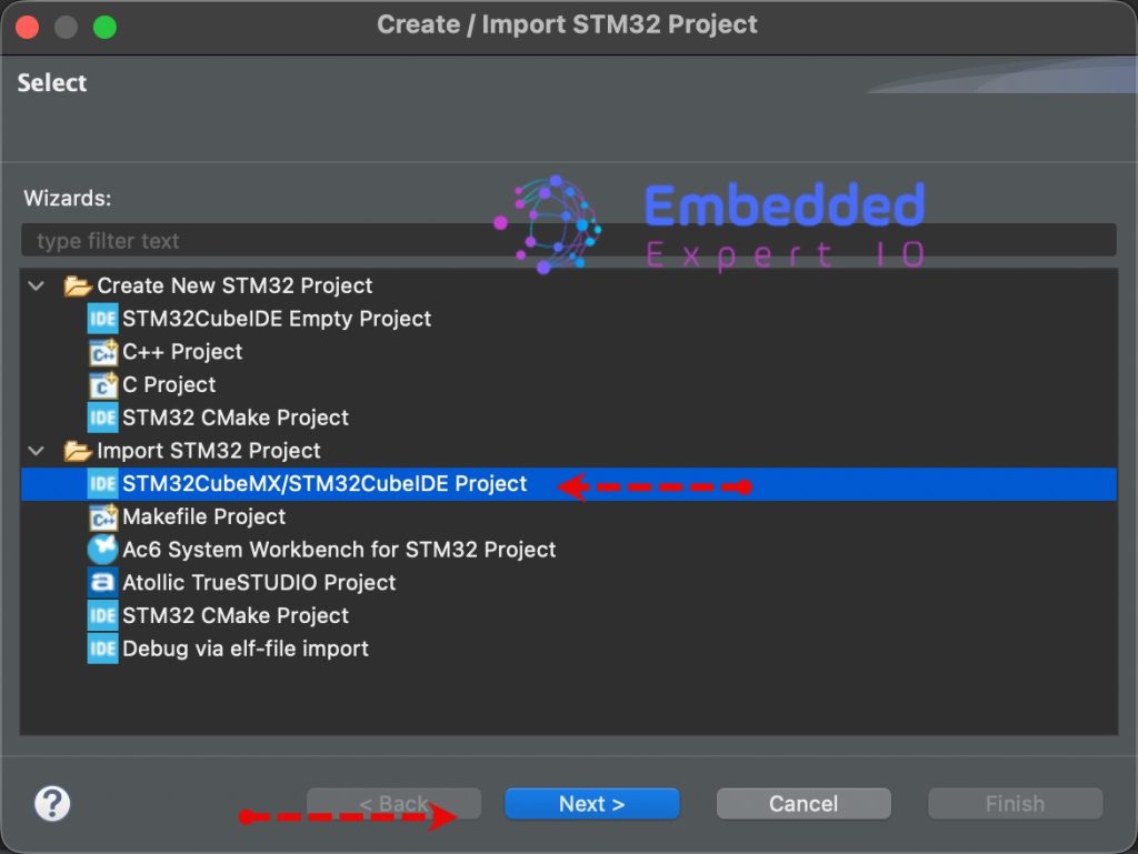
Next, select the folder that contains the .ioc file and click on Finish as follows:

Note: Project name is for reference only.
4. Hardware Setup:
The setup as follows:

The battery and resistor represent power supply and load respectively.
5. Firmware Development:
We start by creating new header and source file with name of INA219.h and INA219.c respectively.
To create the header file, right click on inc folder, and select new, header file as follows:
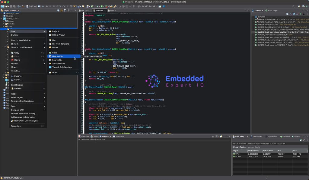
Give it a name INA219.h and click on Finish.
To create new source file, right click on src folder, new and Source file as follows:

Give it INA219.c as a name and click on Finish.
Next, open INA219.h header file and include the following header files:
#include "main.h"
#include "i2c.h"
#include <stdint.h>
#include <stdbool.h>
These will allow us to access the main HAL functions, i2c related functions and standard variables such uint8_t, bool etc.
Ap per the datasheet, the address can be vary depending on the A0 and A1 connection as follows:

Hence, we define the addresses as follows:
/* INA219 I2C address (7-bit). Default = 0x40. HAL expects (addr << 1). */
#define INA219_ADDRESS_GND_GND   (0x40)   /* A0=GND, A1=GND */
#define INA219_ADDRESS_GND_VS    (0x41)
#define INA219_ADDRESS_GND_SDA   (0x42)
#define INA219_ADDRESS_GND_SCL   (0x43)
#define INA219_ADDRESS_VS_GND    (0x44)
#define INA219_ADDRESS_VS_VS     (0x45)
#define INA219_ADDRESS_VS_SDA    (0x46)
#define INA219_ADDRESS_VS_SCL    (0x47)
#define INA219_ADDRESS_SDA_GND   (0x48)
#define INA219_ADDRESS_SDA_VS    (0x49)
#define INA219_ADDRESS_SDA_SDA   (0x4A)
#define INA219_ADDRESS_SDA_SCL   (0x4B)
#define INA219_ADDRESS_SCL_GND   (0x4C)
#define INA219_ADDRESS_SCL_VS    (0x4D)
#define INA219_ADDRESS_SCL_SDA   (0x4E)
#define INA219_ADDRESS_SCL_SCL   (0x4F)
Next, we define the registers as follows:
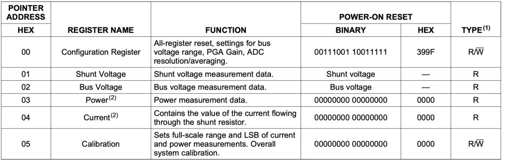
/* Registers */
#define INA219_REG_CONFIGURATION   0x00
#define INA219_REG_SHUNT_VOLTAGE   0x01
#define INA219_REG_BUS_VOLTAGE     0x02
#define INA219_REG_POWER           0x03
#define INA219_REG_CURRENT         0x04
#define INA219_REG_CALIBRATION     0x05
Next, PG gain for the shunt resistor to measure the current:

/* PGA (shunt voltage range) */
typedef enum {
    INA219_PGA_40MV = 0x00,   /* +/- 40 mV, gain 1/8  */
    INA219_PGA_80MV = 0x01,   /* +/- 80 mV, gain 1/4  */
    INA219_PGA_160MV = 0x02,  /* +/- 160 mV, gain 1/2 */
    INA219_PGA_320MV = 0x03   /* +/- 320 mV, gain 1   */
} INA219_PGA_t;
Next, we define the resolution and sample rate as follows:

/* Bus ADC resolution / averaging */
typedef enum {
    INA219_ADC_9BIT   = 0x00,
    INA219_ADC_10BIT  = 0x01,
    INA219_ADC_11BIT  = 0x02,
    INA219_ADC_12BIT  = 0x03,
    INA219_ADC_2SAMP  = 0x09,
    INA219_ADC_4SAMP  = 0x0A,
    INA219_ADC_8SAMP  = 0x0B,
    INA219_ADC_16SAMP = 0x0C,
    INA219_ADC_32SAMP = 0x0D,
    INA219_ADC_64SAMP = 0x0E,
    INA219_ADC_128SAMP = 0x0F
} INA219_ADC_t;
Next, declare the following structure to hold the initialization parameters as follows:
typedef struct {
    I2C_HandleTypeDef *hi2c;
    uint8_t  address;       /* 7-bit address (e.g. 0x40) */
    float    shunt_ohm;     /* shunt resistor value in ohms */
    float    current_lsb;   /* A per LSB (computed from calibration) */
    float    power_lsb;     /* W per LSB (20 * current_lsb) */
} INA219_t;- First is instant for the I2C to be used (i2c1 in this guide).
- Address of the module (0x40, the default one in this guide).
- Resistor values used for the current shunt, 0.1 for this guide.
- Current least significant bit.
- Power least significant bit.
Next, define the following function, this will initialize the the module:
HAL_StatusTypeDef INA219_Init(INA219_t *dev,
                              I2C_HandleTypeDef *hi2c,
                              uint8_t address_7bit,
                              float shunt_resistor_ohm,
                              float max_current_amps);
Next, to reset the module:
HAL_StatusTypeDef INA219_Reset(INA219_t *dev);
Next, to calibrate the current:
HAL_StatusTypeDef INA219_SetCalibration(INA219_t *dev, float max_current);
The following functions to read the bus voltage, shunt voltage, current and power:
HAL_StatusTypeDef INA219_Read_bus_voltage_mv(INA219_t *dev, float *voltage);
HAL_StatusTypeDef INA219_Read_shunt_voltage_mv(INA219_t *dev, float *voltage);
HAL_StatusTypeDef INA219_Read_current_mA(INA219_t *dev, float *current);
HAL_StatusTypeDef INA219_Read_power_mW(INA219_t *dev, float *power);
This will read the raw voltage for the bus:
HAL_StatusTypeDef INA219_Read_bus_voltage_raw(INA219_t *dev, int16_t *raw);
Finally, check if the conversion is read:
bool INA219_ConversionReady(INA219_t *dev);
Hence, the header file as follows:
/* ============================ INA219.h ============================ */
#ifndef __INA219_H
#define __INA219_H

#include "main.h"
#include "i2c.h"
#include <stdint.h>
#include <stdbool.h>

/* INA219 I2C address (7-bit). Default = 0x40. HAL expects (addr << 1). */
#define INA219_ADDRESS_GND_GND   (0x40)   /* A0=GND, A1=GND */
#define INA219_ADDRESS_GND_VS    (0x41)
#define INA219_ADDRESS_GND_SDA   (0x42)
#define INA219_ADDRESS_GND_SCL   (0x43)
#define INA219_ADDRESS_VS_GND    (0x44)
#define INA219_ADDRESS_VS_VS     (0x45)
#define INA219_ADDRESS_VS_SDA    (0x46)
#define INA219_ADDRESS_VS_SCL    (0x47)
#define INA219_ADDRESS_SDA_GND   (0x48)
#define INA219_ADDRESS_SDA_VS    (0x49)
#define INA219_ADDRESS_SDA_SDA   (0x4A)
#define INA219_ADDRESS_SDA_SCL   (0x4B)
#define INA219_ADDRESS_SCL_GND   (0x4C)
#define INA219_ADDRESS_SCL_VS    (0x4D)
#define INA219_ADDRESS_SCL_SDA   (0x4E)
#define INA219_ADDRESS_SCL_SCL   (0x4F)

/* Registers */
#define INA219_REG_CONFIGURATION   0x00
#define INA219_REG_SHUNT_VOLTAGE   0x01
#define INA219_REG_BUS_VOLTAGE     0x02
#define INA219_REG_POWER           0x03
#define INA219_REG_CURRENT         0x04
#define INA219_REG_CALIBRATION     0x05

/* PGA (shunt voltage range) */
typedef enum {
    INA219_PGA_40MV = 0x00,   /* +/- 40 mV, gain 1/8  */
    INA219_PGA_80MV = 0x01,   /* +/- 80 mV, gain 1/4  */
    INA219_PGA_160MV = 0x02,  /* +/- 160 mV, gain 1/2 */
    INA219_PGA_320MV = 0x03   /* +/- 320 mV, gain 1   */
} INA219_PGA_t;

/* Bus ADC resolution / averaging */
typedef enum {
    INA219_ADC_9BIT   = 0x00,
    INA219_ADC_10BIT  = 0x01,
    INA219_ADC_11BIT  = 0x02,
    INA219_ADC_12BIT  = 0x03,
    INA219_ADC_2SAMP  = 0x09,
    INA219_ADC_4SAMP  = 0x0A,
    INA219_ADC_8SAMP  = 0x0B,
    INA219_ADC_16SAMP = 0x0C,
    INA219_ADC_32SAMP = 0x0D,
    INA219_ADC_64SAMP = 0x0E,
    INA219_ADC_128SAMP = 0x0F
} INA219_ADC_t;

typedef struct {
    I2C_HandleTypeDef *hi2c;
    uint8_t  address;       /* 7-bit address (e.g. 0x40) */
    float    shunt_ohm;     /* shunt resistor value in ohms */
    float    current_lsb;   /* A per LSB (computed from calibration) */
    float    power_lsb;     /* W per LSB (20 * current_lsb) */
} INA219_t;

/* API */
HAL_StatusTypeDef INA219_Init(INA219_t *dev,
                              I2C_HandleTypeDef *hi2c,
                              uint8_t address_7bit,
                              float shunt_resistor_ohm,
                              float max_current_amps);

HAL_StatusTypeDef INA219_Reset(INA219_t *dev);
HAL_StatusTypeDef INA219_SetCalibration(INA219_t *dev, float max_current);

HAL_StatusTypeDef INA219_Read_bus_voltage_mv(INA219_t *dev, float *voltage);
HAL_StatusTypeDef INA219_Read_shunt_voltage_mv(INA219_t *dev, float *voltage);
HAL_StatusTypeDef INA219_Read_current_mA(INA219_t *dev, float *current);
HAL_StatusTypeDef INA219_Read_power_mW(INA219_t *dev, float *power);
HAL_StatusTypeDef INA219_Read_bus_voltage_raw(INA219_t *dev, int16_t *raw);
bool               INA219_ConversionReady(INA219_t *dev);

#endif /* __INA219_H */
Next, open INA219.c source file.
We start by including INA219 header file:
#include "INA219.h"
Next, we declare two functions to read/write to/from a register as follows:
static HAL_StatusTypeDef INA219_WriteReg(INA219_t *dev, uint8_t reg, uint16_t value)
{
    uint8_t buf[2];
    buf[0] = (value >> 8) & 0xFF;
    buf[1] = value & 0xFF;

    return HAL_I2C_Mem_Write(dev->hi2c,
                             (dev->address << 1),
                             reg,
                             I2C_MEMADD_SIZE_8BIT,
                             buf, 2, 100);
}

static HAL_StatusTypeDef INA219_ReadReg(INA219_t *dev, uint8_t reg, uint16_t *value)
{
    uint8_t buf[2];
    HAL_StatusTypeDef st;

    st = HAL_I2C_Mem_Read(dev->hi2c,
                          (dev->address << 1),
                          reg,
                          I2C_MEMADD_SIZE_8BIT,
                          buf, 2, 100);

    if (st != HAL_OK) return st;

    *value = ((uint16_t)buf[0] << 8) | buf[1];
    return HAL_OK;
}
Since each register is 16-bit length, we are using internal buffer to handle the two byte read and write.
Next, the function to reset the module:
HAL_StatusTypeDef INA219_Reset(INA219_t *dev)
{
    /* Bit 15 = reset */
    return INA219_WriteReg(dev, INA219_REG_CONFIGURATION, 0x8000);
}
The reset is as simple as setting configuration register back to zero.
Next, set calibration function:
HAL_StatusTypeDef INA219_SetCalibration(INA219_t *dev, float max_current)
{
    /* CAL = 0.04096 / (current_lsb * Rshunt)
       current_lsb chosen so that max_current fits in 15 bits (signed). */
    float current_lsb = max_current / 32767.0f;
    if (current_lsb <= 0.0f) current_lsb = 0.0001f;

    float cal = 0.04096f / (current_lsb * dev->shunt_ohm);
    if (cal > 65535.0f) cal = 65535.0f;
    if (cal < 1.0f)     cal = 1.0f;

    uint16_t cal_reg = (uint16_t)cal;
    /* Recompute actual current_lsb from rounded cal value */
    dev->current_lsb = 0.04096f / (cal_reg * dev->shunt_ohm);
    dev->power_lsb   = 20.0f * dev->current_lsb;

    HAL_StatusTypeDef st = INA219_WriteReg(dev, INA219_REG_CALIBRATION, cal_reg);
    return st;
}
Next, to initialize the module:
HAL_StatusTypeDef INA219_Init(INA219_t *dev,
                              I2C_HandleTypeDef *hi2c,
                              uint8_t address_7bit,
                              float shunt_resistor_ohm,
                              float max_current_amps)
{
    if (dev == NULL || hi2c == NULL) return HAL_ERROR;

    dev->hi2c       = hi2c;
    dev->address    = address_7bit & 0x7F;
    dev->shunt_ohm  = shunt_resistor_ohm;
    dev->current_lsb = 0.0f;
    dev->power_lsb   = 0.0f;

    /* Reset */
    HAL_StatusTypeDef st = INA219_Reset(dev);
    if (st != HAL_OK) return st;
    HAL_Delay(2);

    /* Configuration:
       BRNG   = 1  (32V bus range)
       PG     = INA219_PGA_320MV (11:12)
       BADC   = 12-bit (7:10)
       SADC   = 12-bit (3:6)
       MODE   = 0x07 (shunt & bus, continuous) (0:2)
    */
    uint16_t config = (1u << 13)                              /* BRNG = 32V */
                    | ((uint16_t)INA219_PGA_320MV << 11)     /* PG   */
                    | ((uint16_t)INA219_ADC_12BIT  << 7)     /* BADC */
                    | ((uint16_t)INA219_ADC_12BIT  << 3)     /* SADC */
                    | 0x07;                                   /* MODE */

    st = INA219_WriteReg(dev, INA219_REG_CONFIGURATION, config);
    if (st != HAL_OK) return st;

    /* Apply calibration so current/power registers produce valid data */
    st = INA219_SetCalibration(dev, max_current_amps);
    return st;
}
Next, read bus voltage raw:
HAL_StatusTypeDef INA219_Read_bus_voltage_raw(INA219_t *dev, int16_t *raw)
{
    uint16_t v;
    HAL_StatusTypeDef st = INA219_ReadReg(dev, INA219_REG_BUS_VOLTAGE, &v);
    if (st != HAL_OK) return st;

    /* Clear all flags by masking only the 13 bits that matter, then shift */
    *raw = (int16_t)((v & 0xFFF8) >> 3);

    return HAL_OK;
}
Next, if the module ready to be read as follows:
bool INA219_ConversionReady(INA219_t *dev)
{
    uint16_t v;
    if (INA219_ReadReg(dev, INA219_REG_BUS_VOLTAGE, &v) != HAL_OK) return false;
    /* Bit 1 = Conversion Ready (CNVR) */
    return (v & 0x02) ? true : false;
}
To read the bus voltage in mV:
HAL_StatusTypeDef INA219_Read_bus_voltage_mv(INA219_t *dev, float *voltage)
{
    int16_t raw;
    HAL_StatusTypeDef st = INA219_Read_bus_voltage_raw(dev, &raw);
    if (st != HAL_OK) return st;
    *voltage = raw * 4.0f;     /* LSB = 4 mV */
    return HAL_OK;
}
Read shunt voltage in mV:
HAL_StatusTypeDef INA219_Read_shunt_voltage_mv(INA219_t *dev, float *voltage)
{
    uint16_t v;
    HAL_StatusTypeDef st = INA219_ReadReg(dev, INA219_REG_SHUNT_VOLTAGE, &v);
    if (st != HAL_OK) return st;
    int16_t sv = (int16_t)v;
    *voltage = sv * 0.01f;     /* LSB = 10 uV = 0.01 mV */
    return HAL_OK;
}
Next, read the current in mA:
HAL_StatusTypeDef INA219_Read_current_mA(INA219_t *dev, float *current)
{
    uint16_t v;
    HAL_StatusTypeDef st = INA219_ReadReg(dev, INA219_REG_CURRENT, &v);
    if (st != HAL_OK) return st;
    int16_t raw = (int16_t)v;
    *current = raw * dev->current_lsb * 1000.0f;  /* A -> mA */
    return HAL_OK;
}
Finally, read the power in mW:
HAL_StatusTypeDef INA219_Read_power_mW(INA219_t *dev, float *power)
{
    uint16_t v;
    HAL_StatusTypeDef st = INA219_ReadReg(dev, INA219_REG_POWER, &v);
    if (st != HAL_OK) return st;
    /* power register is unsigned 16-bit, LSB = 20 * current_lsb (in W) */
    *power = v * dev->power_lsb * 1000.0f;  /* W -> mW */
    return HAL_OK;
}
Hence, the source code as follows:
/* ============================ INA219.c ============================ */
#include "INA219.h"

/* ---------- low level helpers ---------- */
static HAL_StatusTypeDef INA219_WriteReg(INA219_t *dev, uint8_t reg, uint16_t value)
{
    uint8_t buf[2];
    buf[0] = (value >> 8) & 0xFF;
    buf[1] = value & 0xFF;

    return HAL_I2C_Mem_Write(dev->hi2c,
                             (dev->address << 1),
                             reg,
                             I2C_MEMADD_SIZE_8BIT,
                             buf, 2, 100);
}

static HAL_StatusTypeDef INA219_ReadReg(INA219_t *dev, uint8_t reg, uint16_t *value)
{
    uint8_t buf[2];
    HAL_StatusTypeDef st;

    st = HAL_I2C_Mem_Read(dev->hi2c,
                          (dev->address << 1),
                          reg,
                          I2C_MEMADD_SIZE_8BIT,
                          buf, 2, 100);

    if (st != HAL_OK) return st;

    *value = ((uint16_t)buf[0] << 8) | buf[1];
    return HAL_OK;
}

/* ---------- public API ---------- */
HAL_StatusTypeDef INA219_Reset(INA219_t *dev)
{
    /* Bit 15 = reset */
    return INA219_WriteReg(dev, INA219_REG_CONFIGURATION, 0x8000);
}

HAL_StatusTypeDef INA219_SetCalibration(INA219_t *dev, float max_current)
{
    /* CAL = 0.04096 / (current_lsb * Rshunt)
       current_lsb chosen so that max_current fits in 15 bits (signed). */
    float current_lsb = max_current / 32767.0f;
    if (current_lsb <= 0.0f) current_lsb = 0.0001f;

    float cal = 0.04096f / (current_lsb * dev->shunt_ohm);
    if (cal > 65535.0f) cal = 65535.0f;
    if (cal < 1.0f)     cal = 1.0f;

    uint16_t cal_reg = (uint16_t)cal;
    /* Recompute actual current_lsb from rounded cal value */
    dev->current_lsb = 0.04096f / (cal_reg * dev->shunt_ohm);
    dev->power_lsb   = 20.0f * dev->current_lsb;

    HAL_StatusTypeDef st = INA219_WriteReg(dev, INA219_REG_CALIBRATION, cal_reg);
    return st;
}

HAL_StatusTypeDef INA219_Init(INA219_t *dev,
                              I2C_HandleTypeDef *hi2c,
                              uint8_t address_7bit,
                              float shunt_resistor_ohm,
                              float max_current_amps)
{
    if (dev == NULL || hi2c == NULL) return HAL_ERROR;

    dev->hi2c       = hi2c;
    dev->address    = address_7bit & 0x7F;
    dev->shunt_ohm  = shunt_resistor_ohm;
    dev->current_lsb = 0.0f;
    dev->power_lsb   = 0.0f;

    /* Reset */
    HAL_StatusTypeDef st = INA219_Reset(dev);
    if (st != HAL_OK) return st;
    HAL_Delay(2);

    /* Configuration:
       BRNG   = 1  (32V bus range)
       PG     = INA219_PGA_320MV (11:12)
       BADC   = 12-bit (7:10)
       SADC   = 12-bit (3:6)
       MODE   = 0x07 (shunt & bus, continuous) (0:2)
    */
    uint16_t config = (1u << 13)                              /* BRNG = 32V */
                    | ((uint16_t)INA219_PGA_320MV << 11)     /* PG   */
                    | ((uint16_t)INA219_ADC_12BIT  << 7)     /* BADC */
                    | ((uint16_t)INA219_ADC_12BIT  << 3)     /* SADC */
                    | 0x07;                                   /* MODE */

    st = INA219_WriteReg(dev, INA219_REG_CONFIGURATION, config);
    if (st != HAL_OK) return st;

    /* Apply calibration so current/power registers produce valid data */
    st = INA219_SetCalibration(dev, max_current_amps);
    return st;
}

HAL_StatusTypeDef INA219_Read_bus_voltage_raw(INA219_t *dev, int16_t *raw)
{
    uint16_t v;
    HAL_StatusTypeDef st = INA219_ReadReg(dev, INA219_REG_BUS_VOLTAGE, &v);
    if (st != HAL_OK) return st;

    /* Clear all flags by masking only the 13 bits that matter, then shift */
    *raw = (int16_t)((v & 0xFFF8) >> 3);

    return HAL_OK;
}

bool INA219_ConversionReady(INA219_t *dev)
{
    uint16_t v;
    if (INA219_ReadReg(dev, INA219_REG_BUS_VOLTAGE, &v) != HAL_OK) return false;
    /* Bit 1 = Conversion Ready (CNVR) */
    return (v & 0x02) ? true : false;
}

HAL_StatusTypeDef INA219_Read_bus_voltage_mv(INA219_t *dev, float *voltage)
{
    int16_t raw;
    HAL_StatusTypeDef st = INA219_Read_bus_voltage_raw(dev, &raw);
    if (st != HAL_OK) return st;
    *voltage = raw * 4.0f;     /* LSB = 4 mV */
    return HAL_OK;
}

HAL_StatusTypeDef INA219_Read_shunt_voltage_mv(INA219_t *dev, float *voltage)
{
    uint16_t v;
    HAL_StatusTypeDef st = INA219_ReadReg(dev, INA219_REG_SHUNT_VOLTAGE, &v);
    if (st != HAL_OK) return st;
    int16_t sv = (int16_t)v;
    *voltage = sv * 0.01f;     /* LSB = 10 uV = 0.01 mV */
    return HAL_OK;
}

HAL_StatusTypeDef INA219_Read_current_mA(INA219_t *dev, float *current)
{
    uint16_t v;
    HAL_StatusTypeDef st = INA219_ReadReg(dev, INA219_REG_CURRENT, &v);
    if (st != HAL_OK) return st;
    int16_t raw = (int16_t)v;
    *current = raw * dev->current_lsb * 1000.0f;  /* A -> mA */
    return HAL_OK;
}

HAL_StatusTypeDef INA219_Read_power_mW(INA219_t *dev, float *power)
{
    uint16_t v;
    HAL_StatusTypeDef st = INA219_ReadReg(dev, INA219_REG_POWER, &v);
    if (st != HAL_OK) return st;
    /* power register is unsigned 16-bit, LSB = 20 * current_lsb (in W) */
    *power = v * dev->power_lsb * 1000.0f;  /* W -> mW */
    return HAL_OK;
}
Next, open main.c file and include tINA219.h header file as follows:
#include "INA219.h"
Declare a structure to hold INA219 parameter as follows:
INA219_t ina;
Next, float values to hold the measured bus voltage, shunt voltage, current and power as follows:
float vbus, vshunt, cur, pwr;
Next, in main function, after the i2c has been initialized, initialize INA219 as follows:
if(INA219_Init(&ina, &hi2c1, 0x40, 0.1f, 3.2f) != HAL_OK)
{
  Error_Handler();
}
Next, in while 1 loop:
if (INA219_ConversionReady(&ina))
{
  INA219_Read_bus_voltage_mv(&ina, &vbus);
  INA219_Read_shunt_voltage_mv(&ina, &vshunt);
  INA219_Read_current_mA(&ina, &cur);
  INA219_Read_power_mW(&ina, &pwr);
}

HAL_Delay(100);
Check if the module is ready to be read then read all the parameters.
Repeat this cycle each 100ms.
Thats all for the guide.
Save, build the project and run it as follows:

You may download the source code from here.
6. Results:
By starting a debugging session, add vbus, vshunt, current and pwr into live expression, you should get something like this:

Power supply:

The results are near to each other. A minor calibration can be done to improve the accuracy.
Stay tuned.
Happy coding 😉

Add Comment