Efficiently parse variable-length incoming data frames by combining UART receive interrupts with the hardware’s built-in IDLE line detection feature. This architecture uses the Read Data Register Not Empty (RXNE) interrupt to collect individual bytes in the background, while the IDLE line interrupt fires automatically as soon as the transmission stops, immediately alerting your firmware that a complete packet has arrived without requiring fixed-length buffers or tedious timeouts.
In this guide, we shall cover the following:
- Introduction.
- Firmware Development.
- Results.
1. Introduction
Receiving data over UART can be significantly more challenging than transmitting it. While transmission is deterministic—your firmware knows exactly how many bytes it intends to send—incoming data from external modules, sensors, or host PCs is often unpredictable. In many real-world applications, messages arrive in variable lengths, meaning your microcontroller cannot rely on a fixed byte-count threshold to determine when a complete packet has safely arrived.
Historically, developers solved this problem using inefficient polling loops or by running a dedicated hardware timer alongside the UART line. This timer would reset on every incoming byte; if it expired, the system assumed the transmission had paused, signaling a frame timeout. While functional, this method consumes valuable hardware timers, introduces unnecessary processing overhead, and adds software complexity.
The STM32F4 provides an elegant, hardware-level solution to this architectural bottleneck: the IDLE Line Detectionfeature.
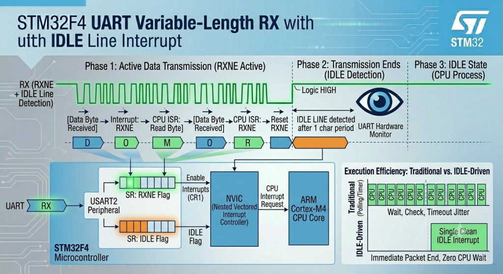
The Mechanics of IDLE Line Detection
The UART protocol dictates that a communication wire rests in a continuous Logic HIGH state when no data is being moved. The STM32 hardware exploits this rule by actively monitoring the RX line during reception.
- Data Phase (RXNE): As a packet arrives, the hardware triggers a Read Data Register Not Empty (RXNE)interrupt for every single byte. Your firmware instantly captures each character and drops it into a ring buffer or linear array in the background.
- Idle Phase (IDLE): The moment the transmitting device finishes sending its payload, the RX line returns to its high state. If the hardware detects that the line remains idle for exactly one full frame period (the time it takes to transmit one start bit, the data payload, and stop bits at your configured baud rate), the microcontroller automatically sets the internal
IDLEstatus flag.
If enabled, this event instantly triggers a specialized interrupt. Instead of guessing when a packet ends or relying on heavy software timeouts, your application is handed a single, clean interrupt the exact moment the transmission ceases. This allows your firmware to immediately freeze the buffer, calculate the exact number of bytes received, and hand the complete packet off to your parsing engines with zero CPU downtime.
2. Firmware Development:
We shall continue from the previous guide from here.
Open main.c of the project, within user code begin PV (Private Variable), declare the following:
#define RXBuffSize 100

char uart_buff_rx[RXBuffSize];
uint16_t rx_index;

uint16_t ReceivedLen;

uint8_t rxDone=0;
First, we declared a buffer size of 100 characters and rx_index to track the received characters.
Furthermore, track how many characters has been received once the IDLE line is detected along side that rxDone to indicate the end of reception once the IDLE line is detected.
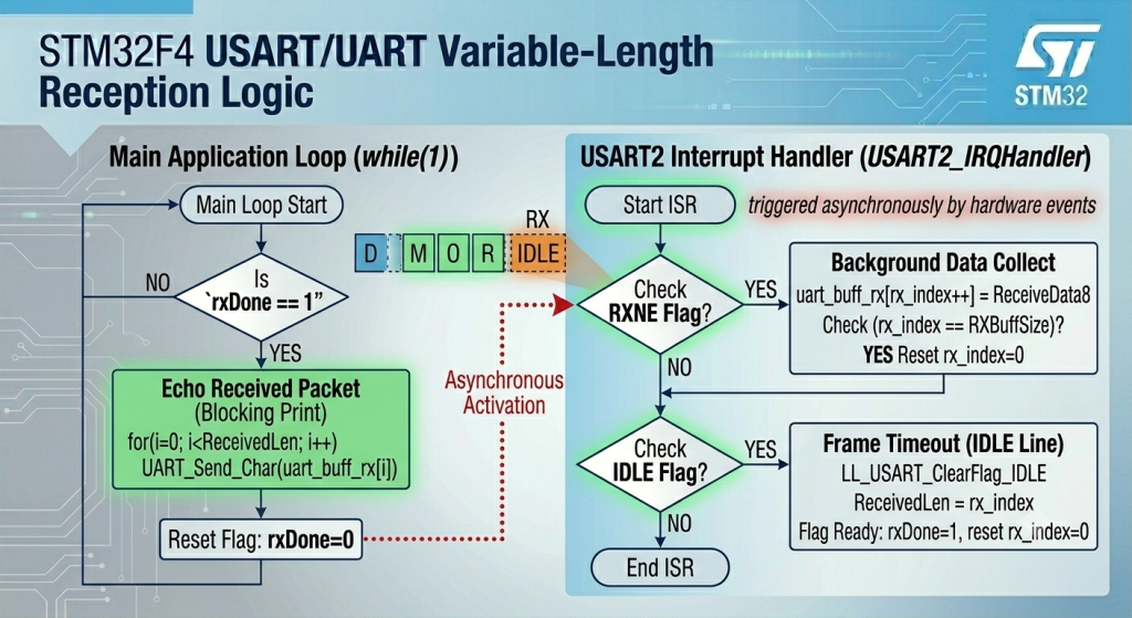
Next, in USART2_IRQHandler function, add the following:
First, handle the incoming character and store it into buffer as follows:
// RXNE interrupt
if (LL_USART_IsActiveFlag_RXNE(USART2))
{
  uart_buff_rx[rx_index++] = LL_USART_ReceiveData8(USART2);
  if(rx_index==RXBuffSize)
  {
    rx_index=0;
  }
}
For the IDLE line:
// IDLE line interrupt
	if(LL_USART_IsActiveFlag_IDLE(USART2))
	{
		LL_USART_ClearFlag_IDLE(USART2);
		ReceivedLen=rx_index;
		rx_index=0;
		rxDone=1;
	}
Please note that reseting the rx_index is determined by your application.
Also, you need to clear the pending flag of IDLE line using the following function:
LL_USART_ClearFlag_IDLE(USART2);
Next, in main function, enable RXNE interrupt along side IDLE line detection as follows:
LL_USART_EnableIT_RXNE(USART2);
LL_USART_EnableIT_IDLE(USART2);
Next, in while 1 loop:
if(rxDone==1)
{
  for (int i=0;i<ReceivedLen;i++)
  {
    UART_Send_Char(uart_buff_rx[i]);
  }
  rxDone=0;
}
Hence, the follow of the code as follows:
Thats all for the firmware.
Save, build and run the project as follows:

You may download the code from here.
3. Results:
Open your favourite terminal and set the baudrate to 115200 and send some data, you should get the data back as follows:
In next part, we shall mix DMA and IDLE line to improve the performance by miles.
Stay tuned.
Happy coding 😉
Add Comment