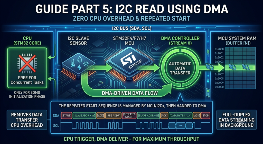
In this fifth part of our STM32 Low-Layer (LL) I2C series, we complete our non-blocking driver suite by leveraging Direct Memory Access (DMA) for memory read operations. We will demonstrate how to configure the DMA controller and manage the I2C Repeated START condition to automatically transfer data directly from a slave device into system RAM without CPU intervention.
In this guide, we shall cover the following:
- Introduction.
- STM32CubeMX setup.
- Firmware development.
- Results.
1. Introduction:
In embedded firmware architecture, retrieving continuous streams of telemetry—such as reading multi-axis accelerometers, sampling environmental sensors, or fetching high-speed ADC data—presents a major hardware management challenge. While writing to a peripheral via I2C is a straight line, reading from a register requires a complex two-phase protocol: first sending a target register address as a Master-Transmitter, and then issuing a Repeated START condition to switch roles into a Master-Receiver.
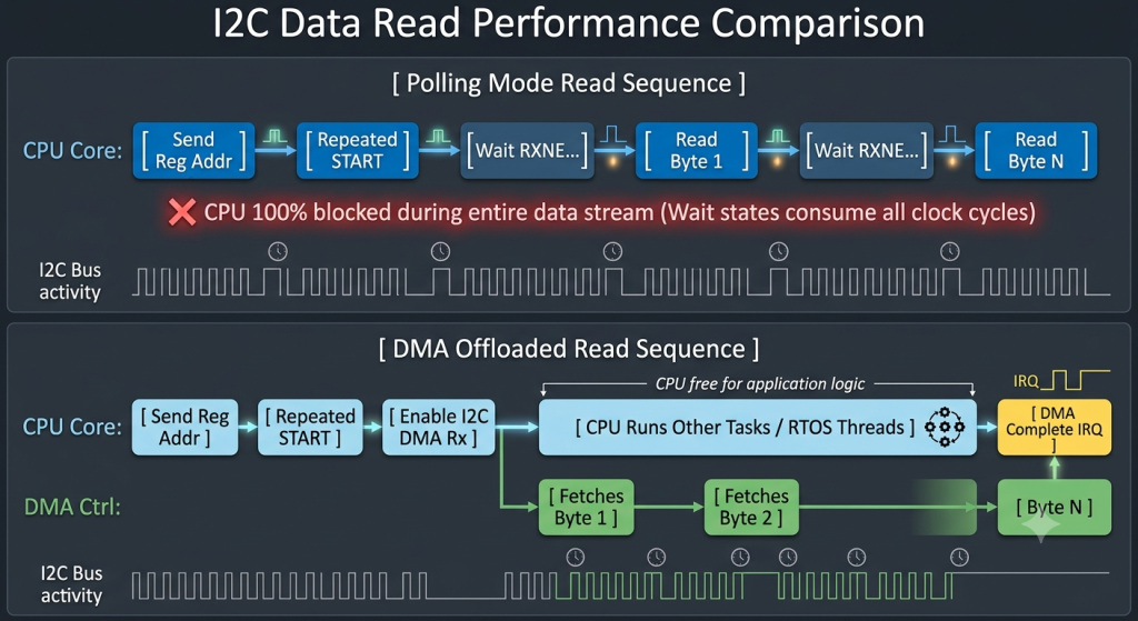
When performed using traditional blocking polling loops, this two-stage read sequence holds the CPU hostage for hundreds of microseconds per transaction. In this fifth installment of our STM32 Low-Layer (LL) I2C series, we complete our non-blocking driver suite by offloading the data reception phase to Direct Memory Access (DMA). We will examine how the STM32 DMA controller automates reading bytes directly from the I2C Receive Data Register (DR) into system RAM with zero processor involvement.
The Mechanics: Why I2C DMA Reads Are Unique
An I2C memory read is inherently more complex than a write operation because it requires a dynamic protocol role switch mid-transaction. The physical bus sequence proceeds as follows:
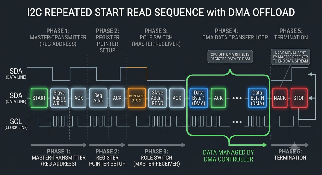
- The Address Phase (CPU Handled): The MCU sends the target slave address with a
WRITEbit, followed by the register memory offset it wants to read. - The Role Switch (Repeated START): Without releasing the bus, the MCU generates a Repeated START condition and re-issues the slave address appended with a
READbit ($LSB = 1$). - The Data Transfer Phase (DMA Handled): Once the slave acknowledges the read request, data streaming begins. This is where DMA takes over completely.
During the reception phase, as each individual byte arrives over the SDA line and shifts into I2C_DR, the hardware automatically raises a Receive Data Register Not Empty (RXNE) signal. Instead of forcing the CPU to sit in a polling loop waiting for RXNE, the signal directly triggers a DMA Request. The DMA controller intercepts this request, reads I2C_DR, and writes the value to designated SRAM memory, automatically incrementing the RAM destination pointer after every byte.
Advantages of Using DMA for I2C Read Operations
While offloading writes prevents CPU lockup during configuration routines, implementing DMA for read sequencesyields even greater system performance benefits in production firmware:
1. High-Frequency Telemetry Buffering
Sensors like IMUs (Inertial Measurement Units), gyroscopes, and pressure gauges often require polling rates anywhere from 100 Hz to 1 kHz. If a system reads 12 bytes of sensor data every millisecond using polling, the CPU spends a substantial percentage of its total execution time waiting for hardware flags. Offloading the read phase to DMA leaves the CPU entirely unburdened, allowing it to spend those free cycles executing complex DSP filters, sensor-fusion math, or control loops.
2. Eliminating Byte Overrun Errors
In fast-paced embedded systems with heavy interrupt activity, a delay in reading I2C_DR can lead to an Overrun Error (OVR), where new incoming data overwrites unread bytes. Because the DMA controller operates on the bus matrix at hardware speed, it clears I2C_DR within clock cycles of the RXNE flag rising. This guarantees that no bytes are dropped, even if high-priority hardware interrupts are firing concurrently on the CPU core.
3. Automatic End-of-Transfer Handling via Hardware
One of the most delicate parts of an I2C read sequence is managing the NACK and STOP signals on the final byte to inform the slave device that transmission is ending. When using STM32 LL drivers alongside DMA, hardware features (such as LL_I2C_EnableDMADeack or the I2C LAST bit) automatically configure the peripheral to automatically generate a NACK on the last byte transferred by the DMA controller.
Polling vs. Interrupts vs. DMA for Data Reception
To frame where DMA sits in a professional system design, consider how different execution strategies handle data reception:
| Strategy | CPU Overhead | Implementation Complexity | Latency / Determinism | Ideal Use Case |
| Polling Mode | High (100%) | Very Low | Poor (Blocks all execution) | Driver bring-up, simple single-byte reads during boot initialization. |
Interrupt Mode (RXNEIRQ) | Medium | Moderate | Moderate (Triggers CPU IRQ per byte) | Low-speed byte reception where DMA channels are needed elsewhere. |
| DMA Mode | Zero | Higher | Excellent (Fully deterministic) | High-rate sensor streaming, multi-byte burst reads, display controllers. |
2. STM32CubeMX Setup:
We shall continue from the previous guide from here.
From Connectivity, select I2C1, DMA settings and add I2C1_RX as follows:
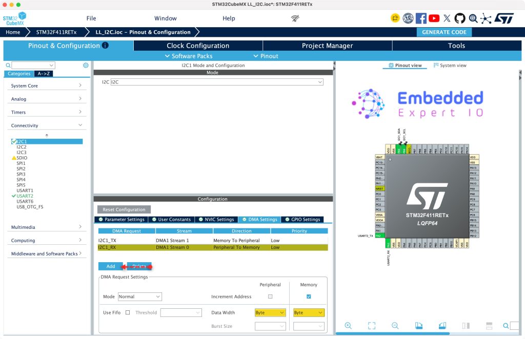
Next, from System Core, NVIC, disable the IRQ handler for DMA1_Stream0 and click on generate code as follows:
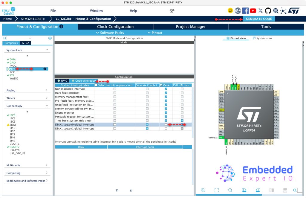
Thats all for the STM32CubeMX configuration.
3. Firmware Development:
Open the project in STM32CubeIDE.
Next, open i2c.h header file and declare the following function:
void I2C_Mem_Read_DMA(I2C_TypeDef *I2Cx, uint8_t slaveAddress, uint16_t regAddress, uint8_t regLen, uint8_t *data, uint16_t length);
This function takes the same parameters as the polling one, with difference that it will use DMA rather than to transmit the data.
Next, open i2c.c source file.
In user code begin 0,
Modify the previous declared DMA_STREAM to the following:
#define I2C_DMA_STREAM_TX LL_DMA_STREAM_1
Next, declare the stream for the RX as follows:
#define I2C_DMA_SREAM_RX LL_DMA_STREAM_0
Next, in user code begin 1, declare the following function:
void I2C_Mem_Read_DMA(I2C_TypeDef *I2Cx, uint8_t slaveAddress, uint16_t regAddress, uint8_t regLen, uint8_t *data, uint16_t length)
Within the function, we shall do some checks:
if (length == 0) return;
if ((regLen != 1) && (regLen != 2)) return;
if (I2C_DMA_Busy) return; /* Prevent overlapping transfers */
These will prevent the function to send incorrect data or overlapping the current transfer.
Next, get the I2C instant and set it to busy as follows:
I2C_DMA_Busy = 1;

/* Save I2C context for the Interrupt Handler */
Active_I2Cx = I2Cx;
Next, prepare the DMA1_Stream0 and clear the pending flags if any as follows:
/* ---- 1. Prepare DMA1 Stream 0 ---- */
LL_DMA_DisableStream(I2C_DMA_INSTANCE, I2C_DMA_SREAM_RX);
while (LL_DMA_IsEnabledStream(I2C_DMA_INSTANCE, I2C_DMA_SREAM_RX)) { /* wait */ }

/* Clear pending DMA flags */
LL_DMA_ClearFlag_TC0(I2C_DMA_INSTANCE);
LL_DMA_ClearFlag_HT0(I2C_DMA_INSTANCE);
LL_DMA_ClearFlag_TE0(I2C_DMA_INSTANCE);
LL_DMA_ClearFlag_FE0(I2C_DMA_INSTANCE);
LL_DMA_ClearFlag_DME0(I2C_DMA_INSTANCE);
Next, set the memory address, peripheral address and number of transfers as follows:
/* Update Memory Address, peripheral address and Data Length for the new payload */
LL_DMA_SetMemoryAddress(I2C_DMA_INSTANCE, I2C_DMA_SREAM_RX, (uint32_t)data);
LL_DMA_SetPeriphAddress(I2C_DMA_INSTANCE, I2C_DMA_SREAM_RX, (uint32_t)&I2Cx->DR);
LL_DMA_SetDataLength(I2C_DMA_INSTANCE, I2C_DMA_SREAM_RX, length);
Next, enable the DMA:
/* Enable DMA Transfer Complete Interrupt */
LL_DMA_EnableIT_TC(I2C_DMA_INSTANCE, I2C_DMA_SREAM_RX);
Next, send the slave address and register to be read from as follows:
This will be in polling mode.
    /* ---- 2. Write phase: Send register address (Polling) ---- */


    LL_I2C_GenerateStartCondition(I2Cx);
    while(!LL_I2C_IsActiveFlag_SB(I2Cx));

    LL_I2C_TransmitData8(I2Cx, (slaveAddress & 0xFE)); // Ensure Write bit (0)
    while(!LL_I2C_IsActiveFlag_ADDR(I2Cx));
    LL_I2C_ClearFlag_ADDR(I2Cx);

    if (regLen == 1)
    {
        LL_I2C_TransmitData8(I2Cx, regAddress & 0xFF);
        while(!LL_I2C_IsActiveFlag_TXE(I2Cx));
    }
    else if (regLen == 2)
    {
        LL_I2C_TransmitData8(I2Cx, (uint8_t)(regAddress >> 8));
        while(!LL_I2C_IsActiveFlag_TXE(I2Cx));

        LL_I2C_TransmitData8(I2Cx, (uint8_t)(regAddress & 0xFF));
        while(!LL_I2C_IsActiveFlag_TXE(I2Cx));
    }
Next, regenerate the start condition to start the reception process as follows:
    /* ---- 3. Read phase: Get data bytes via DMA ---- */
    LL_I2C_GenerateStartCondition(I2Cx);
    while(!LL_I2C_IsActiveFlag_SB(I2Cx));

    LL_I2C_TransmitData8(I2Cx, (slaveAddress | 0x01)); // Ensure Read bit (1)

    while(!LL_I2C_IsActiveFlag_ADDR(I2Cx));
If the length is mover than 1, enable NACK, if it is 1, disable NACK as follows:
    if(length == 1)
    {
        LL_I2C_AcknowledgeNextData(I2Cx, LL_I2C_NACK);
    }
    else
    {
        LL_I2C_AcknowledgeNextData(I2Cx, LL_I2C_ACK);
    }
Finally, arm the DMA to start the reception as follows:
LL_I2C_ClearFlag_ADDR(I2Cx);

/* ---- 4. Arm DMA & I2C DMA Request ---- */
LL_I2C_EnableDMAReq_RX(I2Cx);

/* Start the DMA Stream */
LL_DMA_EnableStream(I2C_DMA_INSTANCE, I2C_DMA_SREAM_RX);
Once the reception is ended, DMA1_Stream0 interrupt will be fired.
For the interrupt handler:
__weak void I2C1_DMA_Rx_Completed(void)
{

}


void DMA1_Stream0_IRQHandler(void)
Within the interrupt handler:
First check if it is transfer completed as follows:
if (LL_DMA_IsActiveFlag_TC0(I2C_DMA_INSTANCE))
If it is. clear the flag:
LL_DMA_ClearFlag_TC0(I2C_DMA_INSTANCE);
Then disable TC interrupt and disable the stream as follows:
/* Disable DMA TC Interrupt and Stream */
LL_DMA_DisableIT_TC(I2C_DMA_INSTANCE, I2C_DMA_SREAM_RX);
LL_DMA_DisableStream(I2C_DMA_INSTANCE, I2C_DMA_SREAM_RX);
Generate the stop condition and disable the DMA request as follows:
/* Terminate I2C Transaction */
LL_I2C_GenerateStopCondition(Active_I2Cx);

/* CRITICAL FIX: Disable RX DMA request */
LL_I2C_DisableDMAReq_RX(Active_I2Cx);
Mark the I2C as free as follows:
I2C_DMA_Busy = 0;
Finally, call I2C1_DMA_Rx completed function which defined as weak function so the user can override it in his firmware as follows:
I2C1_DMA_Rx_Completed();
Hence, the entire block of code as follows:
void I2C_Mem_Read_DMA(I2C_TypeDef *I2Cx, uint8_t slaveAddress, uint16_t regAddress, uint8_t regLen, uint8_t *data, uint16_t length)
{
    if (length == 0) return;
    if ((regLen != 1) && (regLen != 2)) return;
    if (I2C_DMA_Busy) return; /* Prevent overlapping transfers */

    I2C_DMA_Busy = 1;

    /* Save I2C context for the Interrupt Handler */
    Active_I2Cx = I2Cx;

    /* ---- 1. Prepare DMA1 Stream 0 ---- */
    LL_DMA_DisableStream(I2C_DMA_INSTANCE, I2C_DMA_SREAM_RX);
    while (LL_DMA_IsEnabledStream(I2C_DMA_INSTANCE, I2C_DMA_SREAM_RX)) { /* wait */ }

    /* Clear pending DMA flags */
    LL_DMA_ClearFlag_TC0(I2C_DMA_INSTANCE);
    LL_DMA_ClearFlag_HT0(I2C_DMA_INSTANCE);
    LL_DMA_ClearFlag_TE0(I2C_DMA_INSTANCE);
    LL_DMA_ClearFlag_FE0(I2C_DMA_INSTANCE);
    LL_DMA_ClearFlag_DME0(I2C_DMA_INSTANCE);


    /* Update Memory Address, peripheral address and Data Length for the new payload */
    LL_DMA_SetMemoryAddress(I2C_DMA_INSTANCE, I2C_DMA_SREAM_RX, (uint32_t)data);
    LL_DMA_SetPeriphAddress(I2C_DMA_INSTANCE, I2C_DMA_SREAM_RX, (uint32_t)&I2Cx->DR);
    LL_DMA_SetDataLength(I2C_DMA_INSTANCE, I2C_DMA_SREAM_RX, length);

    /* Enable DMA Transfer Complete Interrupt */
    LL_DMA_EnableIT_TC(I2C_DMA_INSTANCE, I2C_DMA_SREAM_RX);

    /* ---- 2. Write phase: Send register address (Polling) ---- */


    LL_I2C_GenerateStartCondition(I2Cx);
    while(!LL_I2C_IsActiveFlag_SB(I2Cx));

    LL_I2C_TransmitData8(I2Cx, (slaveAddress & 0xFE)); // Ensure Write bit (0)
    while(!LL_I2C_IsActiveFlag_ADDR(I2Cx));
    LL_I2C_ClearFlag_ADDR(I2Cx);

    if (regLen == 1)
    {
        LL_I2C_TransmitData8(I2Cx, regAddress & 0xFF);
        while(!LL_I2C_IsActiveFlag_TXE(I2Cx));
    }
    else if (regLen == 2)
    {
        LL_I2C_TransmitData8(I2Cx, (uint8_t)(regAddress >> 8));
        while(!LL_I2C_IsActiveFlag_TXE(I2Cx));

        LL_I2C_TransmitData8(I2Cx, (uint8_t)(regAddress & 0xFF));
        while(!LL_I2C_IsActiveFlag_TXE(I2Cx));
    }

    /* ---- 3. Read phase: Get data bytes via DMA ---- */
    LL_I2C_GenerateStartCondition(I2Cx);
    while(!LL_I2C_IsActiveFlag_SB(I2Cx));

    LL_I2C_TransmitData8(I2Cx, (slaveAddress | 0x01)); // Ensure Read bit (1)

    while(!LL_I2C_IsActiveFlag_ADDR(I2Cx));

    /* CRITICAL I2C DMA READ RULE:
       To properly receive N bytes via DMA, NACK must be set BEFORE clearing ADDR flag.
       If length == 1, set NACK. If length > 1, set ACK, but DMA/Peripheral will handle NACK
       for the last byte if EVERR/TCIE is managed.
       Simplification for DMA: Set NACK before clearing ADDR */
    if(length == 1)
    {
        LL_I2C_AcknowledgeNextData(I2Cx, LL_I2C_NACK);
    }
    else
    {
        LL_I2C_AcknowledgeNextData(I2Cx, LL_I2C_ACK);
    }

    LL_I2C_ClearFlag_ADDR(I2Cx);

    /* ---- 4. Arm DMA & I2C DMA Request ---- */
    LL_I2C_EnableDMAReq_RX(I2Cx);

    /* Start the DMA Stream */
    LL_DMA_EnableStream(I2C_DMA_INSTANCE, I2C_DMA_SREAM_RX);
}


__weak void I2C1_DMA_Rx_Completed(void)
{

}


void DMA1_Stream0_IRQHandler(void)
{
    if (LL_DMA_IsActiveFlag_TC0(I2C_DMA_INSTANCE))
    {
        LL_DMA_ClearFlag_TC0(I2C_DMA_INSTANCE);

        /* Disable DMA TC Interrupt and Stream */
        LL_DMA_DisableIT_TC(I2C_DMA_INSTANCE, I2C_DMA_SREAM_RX);
        LL_DMA_DisableStream(I2C_DMA_INSTANCE, I2C_DMA_SREAM_RX);

        /* Terminate I2C Transaction */
        LL_I2C_GenerateStopCondition(Active_I2Cx);

        /* CRITICAL FIX: Disable RX DMA request */
        LL_I2C_DisableDMAReq_RX(Active_I2Cx);

        /* Mark transfer as complete */
        I2C_DMA_Busy = 0;

        I2C1_DMA_Rx_Completed();
    }
}
Next, open main.c file.
In user code begin 0, declare the following volatile:
volatile uint8_t I2C_Rx_Completed=0;
This will signal the firmware that the Rx process is completed and ready for processing.
Next, declare I2C1_DMA_Rx_Completed as follows:
void I2C1_DMA_Rx_Completed(void)
{
	I2C_Rx_Completed=1;
}
In user code begin 3 in while loop, replace the reading using polling to reading using DMA and wait for the transfer to complete as follows:
I2C_Mem_Read_DMA(I2C1,ds3231_addr,0x00,1,RTCData,3);

while(I2C_Rx_Completed==0);
I2C_Rx_Completed=0;
The rest of the code will remain the same.
Thats all for the firmware.
Save, build the project and run it as follows:

You may download the project file from here.
4. Results:
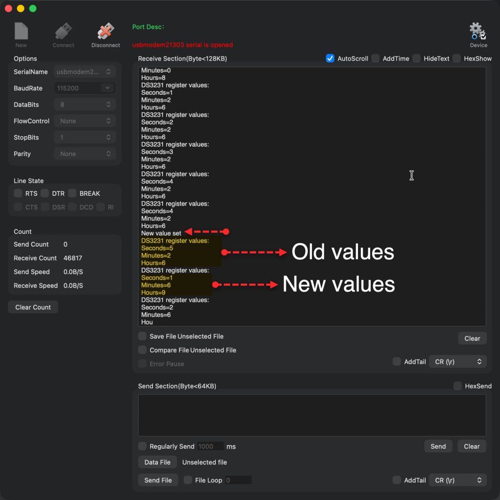
Open your serial terminal and you should something like this:
Stay tuned.
Happy coding 😉

Add Comment