
In this fifth part of the guide, we connect the web user interface to the STM32 hardware peripherals to enable real interaction with the system. This demonstrates how browser-based controls can monitor and manipulate embedded resources, bridging the gap between the device firmware and the user-facing interface.
In this guide, we shall cover the following:
- Hardware setup.
- STM32CubeMX configuration.
- Firmware Development.
- Results.
1. Hardware Setup:
The hardware setup as follows:
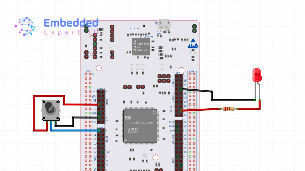
Note: Resistor value is 220Ohm.
The connection as follows:
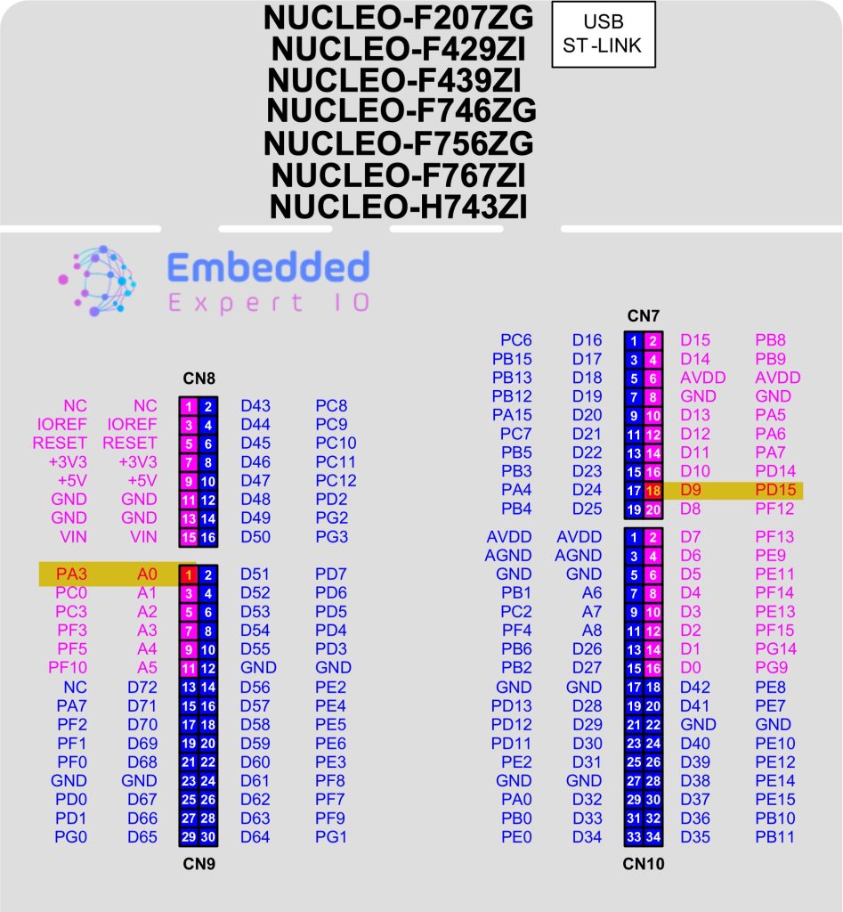
The external LED is connected to PD15 (D9 of Arduino header) while the potentiometer is connected to PA3 (A0 of Arduino header).
2. STM32CubeMX Configuration:
Open the .ioc file using STM32CubeMX.
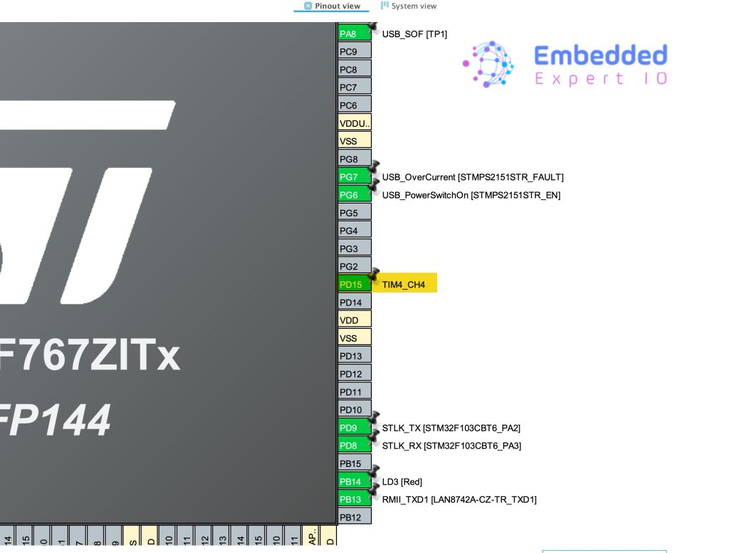
Set PD15 as TIM4_CH4 as follows:
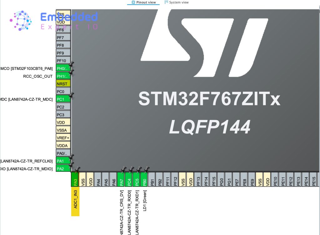
Additionally, configure PA3 as ADC1_IN3 as follows:
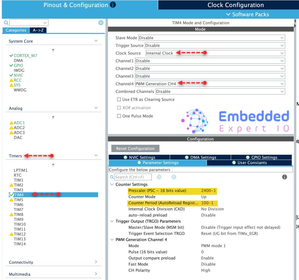
From Pinout and Configuration, Timers, select TIM4 and configure it as follows:
- Clock Source to be internal Clock.
- Channel 3 set it as PWM Generation CH4.
- Prescaler to 2400-1.
- Counter Period to 100-1.
For more information about how to configure PWM and the parameters, please refer to this guide.
Finally, click on Generate Code to generate the new configuration.

3. Firmware Development:
With the peripherals configured, we now move to the actual code. The generated project already has most of the Mongoose networking code in place. We only need to focus on two files: main.c and mongoose_glue.c.
The mongoose_glue.c file is the bridge between the web UI and the hardware. It contains getter and setter functions for each API endpoint we defined in the wizard. These functions are called automatically by Mongoose whenever the UI state changes. We fill in the hardware control code inside them.
The generated mongoose_glue.c file already has glue_set_leds and glue_get_leds functions. We could write our code directly inside them, but the problem is that mongoose_glue.c gets overwritten every time the Mongoose Wizard regenerates the project. Any code we wrote inside it will be lost.
The better approach is to define our own getter and setter functions in main.c and register them using mongoose_set_http_handlers. Our code stays safe in main.c and is never touched by the wizard.
We start by defining two function for led setter and led getter as follows:
In user code begin 0 after mg_random function, declare the getter function as follows:
void get_leds(struct leds * LEDs)
Within the function, read each LED state and store it in leds structure as follows:
LEDs->led1=(HAL_GPIO_ReadPin(LD1_GPIO_Port, LD1_Pin));
LEDs->led2=(HAL_GPIO_ReadPin(LD2_GPIO_Port, LD2_Pin));
LEDs->led3=(HAL_GPIO_ReadPin(LD3_GPIO_Port, LD3_Pin));
LD1, LD2 and LD3 are the built-in LEDs in Nucleo board.
Next, getter function for PWM:
void get_pwm(struct PWM *pwm)
{
	pwm->value=__HAL_TIM_GET_COMPARE(&htim4, TIM_CHANNEL_4);

}
Setter function for PWM:
void set_PWM(struct PWM *pwm)
{
	__HAL_TIM_SET_COMPARE(&htim4, TIM_CHANNEL_4, pwm->value);


}
For the ADC, since the UI never reads the ADC gauge, only getter function is needed.
To display the ADC value on the gauge, we need to follows these steps:
- Read the ADC.
- Scale the ADC value to represent 0 to 100.
- Update the gauge.
First, a function that will scale the ADC read:
long map(long x, long in_min, long in_max, long out_min, long out_max) {
  return (x - in_min) * (out_max - out_min + 1) / (in_max - in_min + 1) + out_min;
}
Note: this is the same function used by Arduino which is called map.
Next, read ADC function:
int readADC(void)
{
  HAL_ADC_Start(&hadc1);
  HAL_ADC_PollForConversion(&hadc1, 100);
  uint16_t ADC_VAL = HAL_ADC_GetValue(&hadc1);
  HAL_ADC_Stop(&hadc1);
  uint16_t val = map(ADC_VAL, 0, 4095, 0, 100);
  return val;
}
For more information how to read the ADC in polling mode, please refer to this guide.
Getter function for the gauge:
void get_ADC_Value(struct ADC_Value * adcData)
{
	adcData->adc_value=readADC();
}
Next, before mongoose initialization, start the timer in PWM mode as follows:
HAL_TIM_PWM_Start(&htim4, TIM_CHANNEL_4);
After the mongoose initialization, link the led getter and setter function for the LEDs as follows:
mongoose_set_http_handlers("leds", get_leds, set_leds);Please note that the “leds” should have the same structure name which is leds in this case.
Link the getter and setter functions for PWM as follows:
mongoose_set_http_handlers("PWM", get_pwm, set_PWM);For ADC:
mongoose_set_http_handlers("ADC_Value", get_ADC_Value, NULL);Since we want to update the gauge regularly, we need to use websocket to update the gauge as follows:
mongoose_add_ws_reporter(200, "ADC_Value");
This will update the gauge each 200ms.
Thats all for the firmware.
Save, build and run the project as follows:

4. Results:
Using the IP address provided by the router, enter it to the web browser and you should get the following:
To download the project:
Happy coding 😉
Add Comment