By offloading time management to the SysTick timer interrupt, you can replace blocking delays with a non-blocking, interrupt-driven time base that keeps your CPU free for other tasks. This guide demonstrates how to configure the 24-bit SysTick counter using Low Layer (LL) functions to increment a global millisecond counter for precise application timing.
In this guide, we shall cover the following:
- Introduction.
- STM32CubeMX setup.
- Importing project to STM32CubeIDE.
- Firmware Development.
- Results.
1. Introduction:
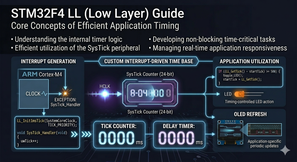
The Power of Deterministic Timing: Understanding the SysTick Timer
In the realm of real-time embedded systems, time is the most critical resource. While initial projects often rely on “blocking” delays—where the processor sits in a useless loop wasting millions of clock cycles—professional firmware requires a non-blocking time base. This is where the SysTick (System Tick) timer becomes indispensable. Integrated directly into the ARM Cortex-M4 core of your STM32F411, the SysTick is a 24-bit down-counter specifically designed to provide a consistent heartbeat for the processor, independent of complex peripheral timers.
Why an Interrupt-Driven Time Base Matters
Using Low Layer (LL) drivers to configure the SysTick interrupt allows you to shift from a “synchronous” mindset to an “asynchronous” one. Instead of the CPU being held hostage by a delay() function, the SysTick timer triggers an Interrupt Service Routine (ISR) at regular intervals (typically every 1 millisecond). This heartbeat allows you to:
- Multi-task efficiently: You can check for button presses, update displays, and run state machines based on a global
uwTickvariable while the main loop continues to execute other logic. - Achieve Precise Periodicity: Unlike software loops, which vary in speed based on compiler optimizations or CPU frequency, the SysTick interrupt is tied directly to the hardware clock, ensuring that “1 millisecond” remains exactly that.
- Reduce Power Consumption: A dedicated time base allows the processor to enter low-power modes between tasks, waking up only when the timer indicates it is time to perform an action.
LL Drivers vs. Middleware Timing
While many developers use the standard HAL_Delay(), implementing your own time base using LL drivers provides a deeper understanding of the exception-handling mechanism of the Cortex-M4. By manually initializing the tick frequency with LL_Init1msTick and defining the SysTick_Handler, you eliminate the overhead of the HAL state machine. This lean approach is essential for high-performance applications where you need to minimize the “latency” between a timer event and the execution of your code.
In this guide, we will transform your STM32F411 from a device that “waits” into a device that “schedules,” creating a robust foundation for everything from debouncing buttons to complex sensor sampling.
2. STM32CubeMX setup:
Open STM32CubeMX as start a new project as follows:
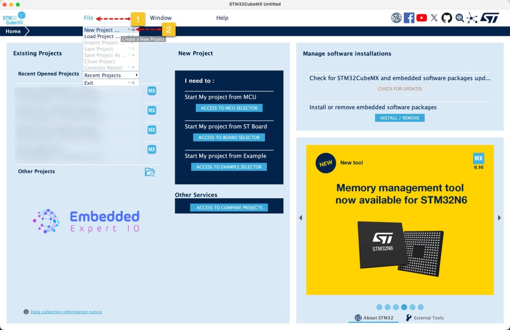
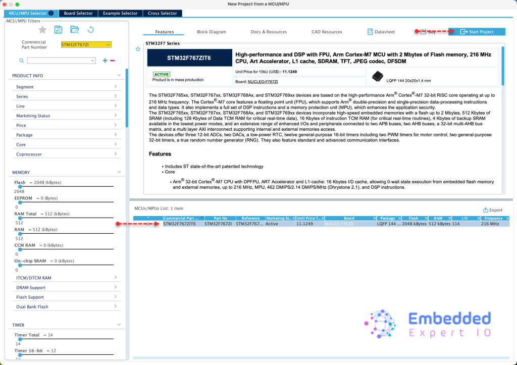
Search for your STM32 MCU, select the MCU and click on Start New Project as follows:
This guide shall use STM32F767Zi Nucleo-144 board
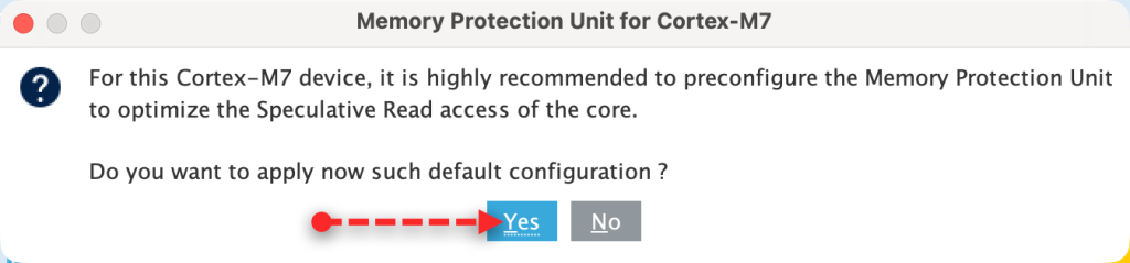
Since STM32F7 is an ARM Cortex M7, it requires to setup the cache, we shall go with the default setup since we don’t care about it right now.
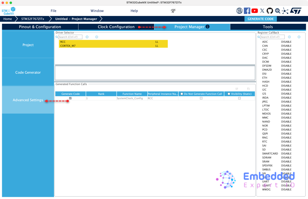
Next, we don’t need to do anything extra. From Project Manager tab, Advanced Settings, set both, RCC and Cortex M7 to LL as follows:
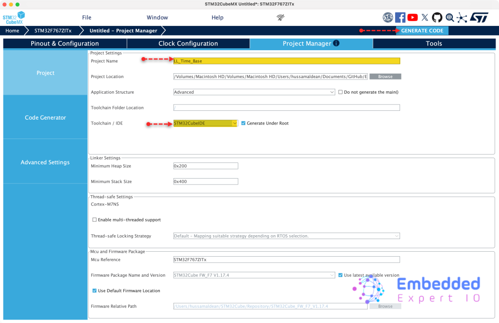
Next, from Project, set toolchain/IDE to STM32CubeIDE, give the project a name and click generate code as follows:
Thats all for STM32CubeMX setup.
3. Importing Project to STM32CubeMX:
Open STM32CubeIDE, select your workspace and click on Launch.
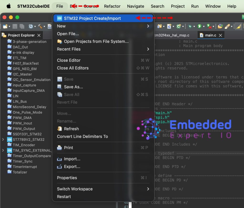
From the IDE, click File and select STM32 Project Create/Import as follows:
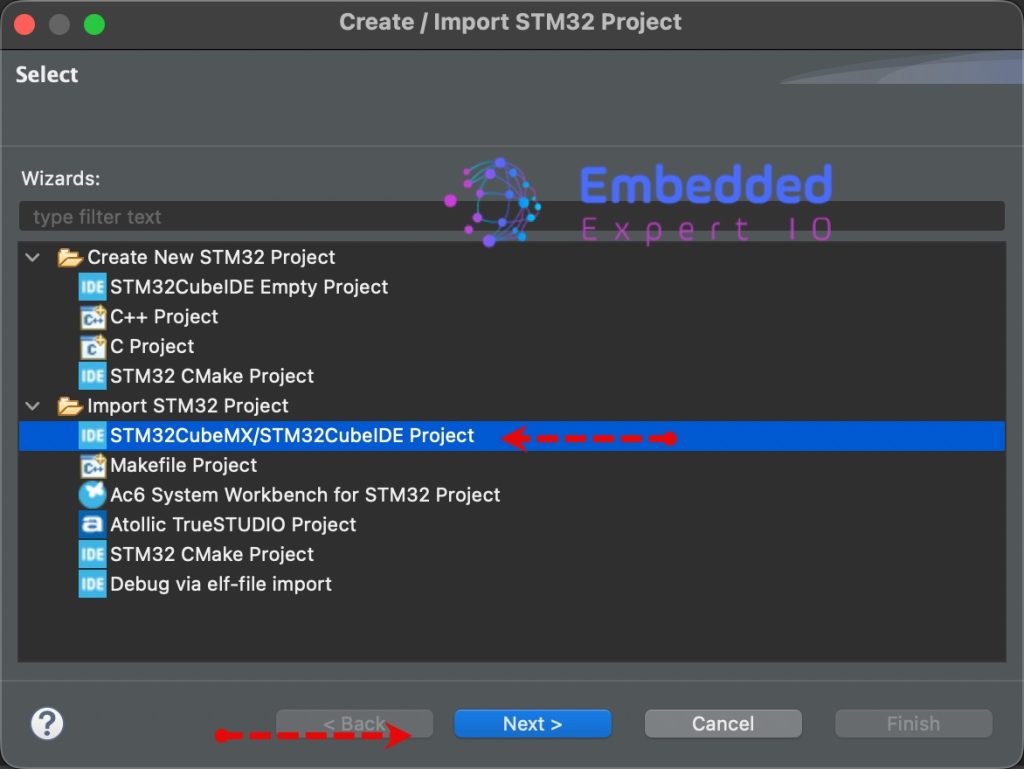
Next, from Import STM32 Project, select STM32CubeMX/STM32CubeIDE Project and click on Next as follows:
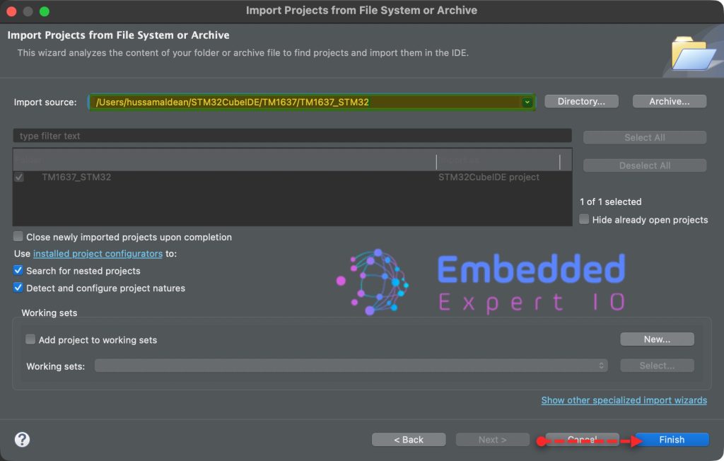
Next, select the folder that contains the .ioc file and click on Finish as follows:
Note: Project name is for reference only.
4. Firmware Development:
From project explorer, open stm32f7xx_it.c fro src folder.
In the source file, in user code begin PV, declare the following variable:
volatile uint32_t ticks=0;
This will hold the current ticks generated each 1ms from SysTick interrupt.
Within same source, in user code begin 0, declare the following two functions:
uint32_t getCurrentTicks(void)
{
	uint32_t temp_ticks=ticks;
	return temp_ticks;
}

static void TickInc(void)
{
	ticks++;
}
These two functions serve as the software interface for your custom time base, acting as the bridge between the hardware interrupt and your application logic.
getCurrentTicks
This is a getter function used to safely retrieve the current system time.
- Purpose: It returns the total number of milliseconds elapsed since the processor started (or since the counter last rolled over).
- Safe Access: By assigning
ticksto a localtemp_ticksvariable before returning, it provides a consistent snapshot of the time for the caller, ensuring that even if an interrupt occurs during the return process, the logic remains predictable.
TickInc
This is the incrementer function, typically called from within the SysTick_Handler interrupt service routine.
- Purpose: It performs the actual “work” of the time base by incrementing the global
ticksvariable by 1. - Static Scope: Marked as
static, this function is private to the file where it is defined, preventing other parts of the code from accidentally modifying the system clock and ensuring that only the intended hardware trigger can advance time.
Next, in void SysTick_Handler(void) in USER CODE BEGIN SysTick_IRQn 0, call TickInc function as follows:
void SysTick_Handler(void)
{
  /* USER CODE BEGIN SysTick_IRQn 0 */
	TickInc();
  /* USER CODE END SysTick_IRQn 0 */

  /* USER CODE BEGIN SysTick_IRQn 1 */

  /* USER CODE END SysTick_IRQn 1 */
}
Next, in stm32f7xx_it.h header file, in USER CODE BEGIN EFP, include getCurrentTicks function as follows:
uint32_t getCurrentTicks(void);
Finally, in main.c file, we start by including stm32f7xx_it.h as follows:
#include "stm32f7xx_it.h"
In user code begin PV, declare the following variable:
uint32_t currentTicks=0;
Next, in main function, in USER CODE BEGIN SysInit, enable SysTick interrupt as follows:
SysTick->CTRL|=SysTick_CTRL_TICKINT_Msk;
Next, in user code begin 3 in while 1 loop:
currentTicks=getCurrentTicks();
Get the current ticks and store it in CurrentTicks variable.
Thats all for the firmware.
Thats all for the firmware.
Save, build the project and run it as follows:

5. Results:
Open a debugging session, add currentTicks to Live Expressions and run the project.
You should get the following:
Thats all for this guide.
Happy coding 😉
Add Comment