In this first part, we will introduce the ST7789V2 display controller, its key features, and how it interfaces with STM32 microcontrollers. We will also walk through setting up the STM32 project in CubeMX to prepare the foundation for driving the display.
In this guide, we shall cover the following:
- Introduction.
- Hardware connection.
- STM32CubeMX setup.
- Importing project to STM32CubeIDE.
1. Introduction:
In this first part of the guide, we will take a deep, foundational look at the ST7789V2 display controller, a highly integrated and widely used driver IC that powers a broad range of modern TFT-LCD modules. The ST7789V2 belongs to the ST77xx family and is designed specifically for 240×240, 240×320, and similar small-to-medium resolutions, making it ideal for compact embedded devices such as smart watches, handheld instruments, industrial HMIs, test equipment, home appliances, IoT dashboards, and any system that requires vivid color graphics in a small form factor. The controller integrates nearly everything required to operate a TFT panel, including a sophisticated display timing engine, internal GRAM memory, a flexible command set, backlight control support, and multiple interface options, allowing the display to operate with minimal external components and very low MCU overhead.
The ST7789V2’s feature set is one of the main reasons it has become so dominant in the embedded space. It supports a 65K/262K color depth, a high-speed SPI interface (1-, 2-, or 3-line variants), and a parallel interface on some modules, giving developers the flexibility to choose the most suitable communication method for their design constraints. The controller includes a full frame buffer (GRAM) inside the chip itself, meaning the STM32 does not need to allocate large sections of internal RAM for storing raw display data. This makes the ST7789V2 particularly attractive for MCUs with limited memory. Additionally, its built-in display-driving logic handles complex tasks such as display refresh, tearing effect synchronization, data format conversion, vertical scrolling, partial mode operation, inversion control, gamma correction, sleep modes, and pixel addressing, allowing the microcontroller to focus on higher-level graphics tasks.
On the LCD side, a typical ST7789V2-based TFT module uses an IPS or TFT panel with vibrant colors, wide viewing angles, and good brightness characteristics. These modules often come in sizes ranging from 1.3″ to 2.0″ or 2.4″, making them extremely common in portable devices. Their applications span across numerous fields: wearables, UI panels, oscilloscope interfaces, multimeters, battery chargers, control units, vehicle dashboards, smart home controllers, HVAC thermostats, 3D printer screens, and even consumer gadgets like music players and gaming handhelds. The ease of interfacing, combined with the mature and well-documented command set, makes the ST7789V2 a practical choice for both hobbyists and professionals building performance-critical graphical systems.
Because the ST7789V2 is so flexible, understanding how it communicates and how to configure it is essential before writing any driver code. Different modules may expose different interfaces—most commonly SPI, though some versions support an 8080-style parallel bus, which offers higher throughput at the cost of more pins. SPI-based modules often operate at speeds up to 40–80 MHz depending on board layout, allowing for fast pixel pushing even without hardware accelerators. The display’s initialization sequence must be carefully implemented because ST7789V2 commands control multiple layers of the display pipeline, including pixel formats (RGB565/666), column/page address ranges, MADCTL orientation settings, porch timings, frame rates, gate driver settings, and voltage configurations. This guide aims to remove the confusion by providing a clear, step-by-step setup process from project configuration to full display activation.
Before touching a single line of display code, the STM32 environment must be properly configured. That is why the second portion of this first chapter will focus on setting up a clean and well-structured project in STM32CubeMX, ensuring all relevant peripherals and system clocks are correctly initialized for optimal performance. We will go over choosing the right communication interface for your display module, configuring GPIOs for control signals such as DC (Data/Command), RST (reset), CS (chip select), BLK (backlight), and SPI pins, and enabling the correct clock speeds to avoid bottlenecks later in the application. We will also discuss recommended SPI settings, DMA considerations, HAL vs. LL options, and how to organize the project so future display functions can be added cleanly and efficiently.
By the end of this part, you will have a full understanding of the ST7789V2’s capabilities and architecture, understand where it fits in real-world applications, and be fully prepared with a correctly configured STM32CubeMX project ready to move forward to Part 2, where we will begin writing the initialization sequence, low-level driver code, and the first routines for sending commands and pixel data to the display.
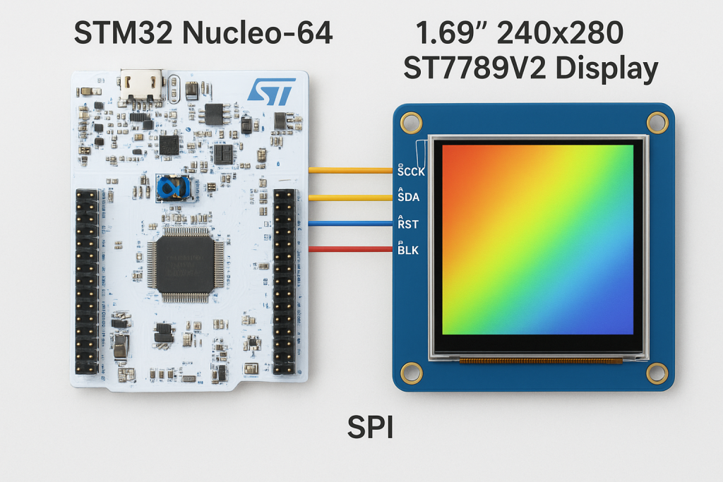
2. Hardware Connection:
The connection as follows:
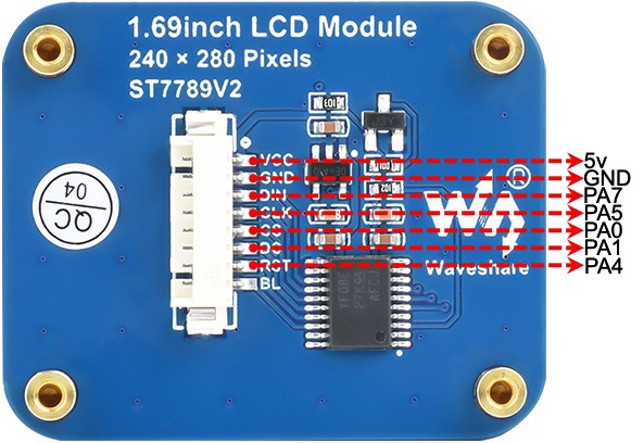
| 1.69inch LCD Module | STM32F411 Nucleo-64 |
| Vcc | 5V |
| GND | GND |
| DIN | PA7 (D11 of Arduino) |
| CLK | PA5 (D13 of Arduino) |
| CS | PA0 (A0 of Arduino) |
| DC | PA1 (A1 of Arduino) |
| RST | PA4 (A2 of Arduino) |
Note: BL is optional, you can leave it floating or connect PWM signal to control the brightness.
3. STM32CubeMX Setup:
Open STM32CubeMX as start a new project as follows:
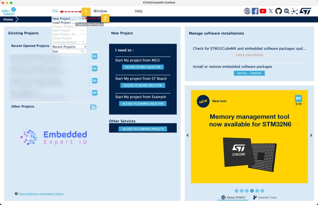
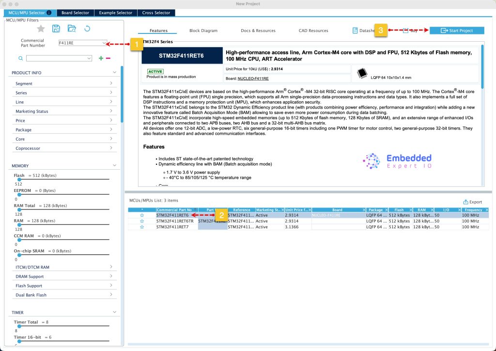
Search for your STM32 MCU, select the MCU and click on Start New Project as follows:
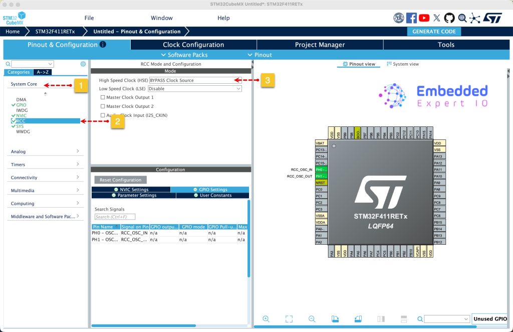
Next, from system core, select RCC and select either Crystal / Ceramic oscillator in case your board has external oscillator or bypass the oscillator in case of Nucleo board. Since this guide uses STM32F411 Nucleo-64, bypass oscillator will be used as follows:
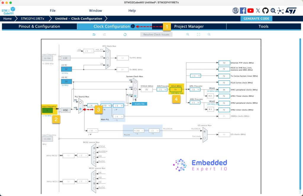
Next, from Clock configuration, set the input frequency to 8MHz, PLL source to HSE and set HCLK frequency to 72MHz. Press enter to set the correct parameters.
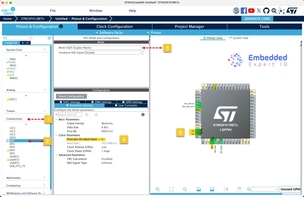
Next, from connectivity, select SPI and set it to master half duplex, set the prescaler to 4. By selecting this, the SPI clock will be 18MHz, good enough given the setup.
Also, set PA0, PA1 and PA4 as output and give then name of CS, DC and RST respectively.
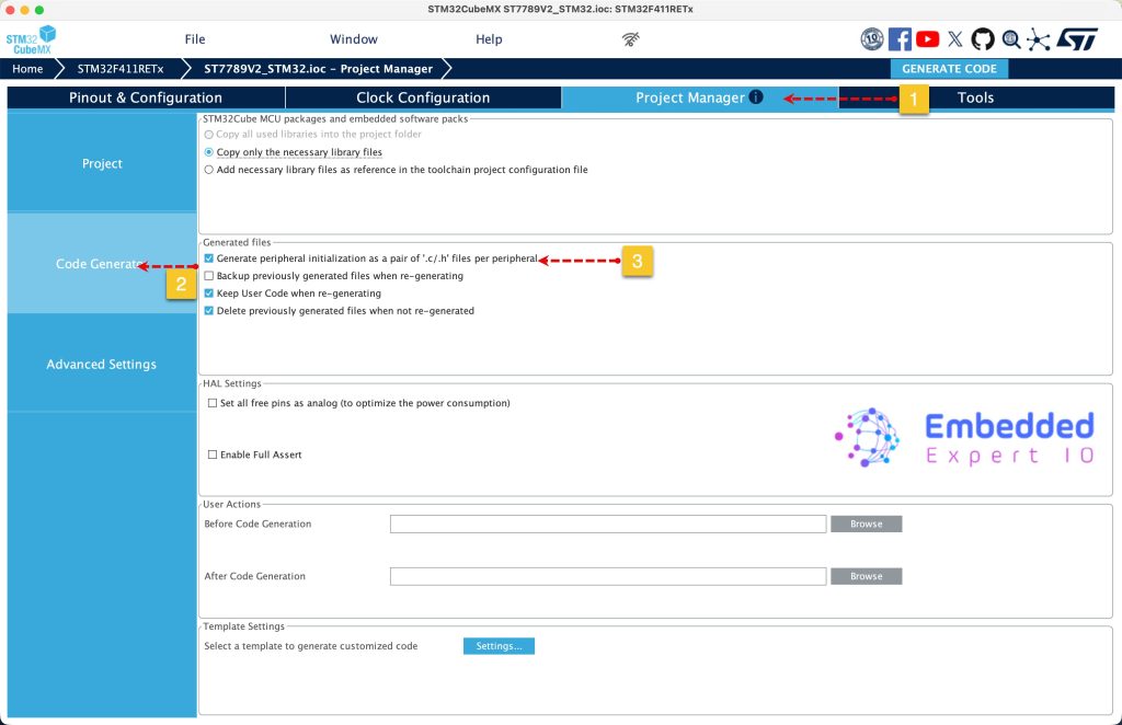
Next, from project manager, select code generation and set generation the peripherals initialization as pair of .c/.h files as follows:
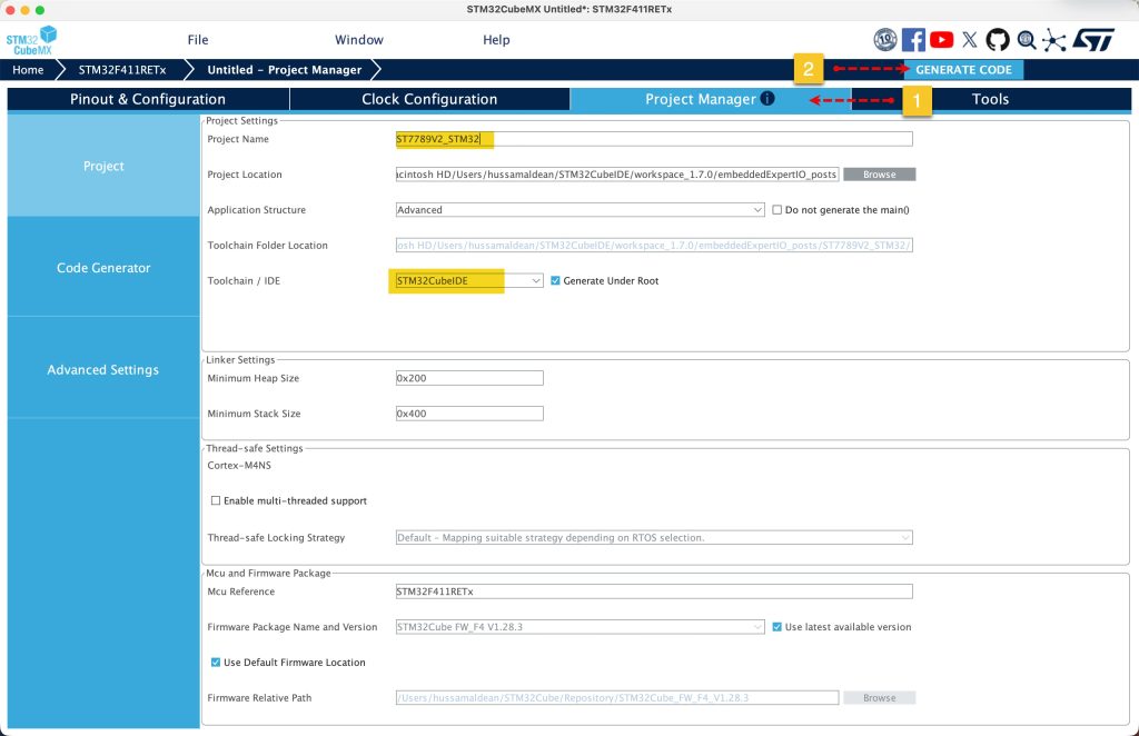
Next, from Project, give the project a name, select the location of the project, select toolchain/IDE to STM32CubeIDE and click on Generate Code as follows:
This will generate the project.
4. Import Project to STM32CubeIDE:
Open STM32CubeIDE, select your workspace and click on Launch.
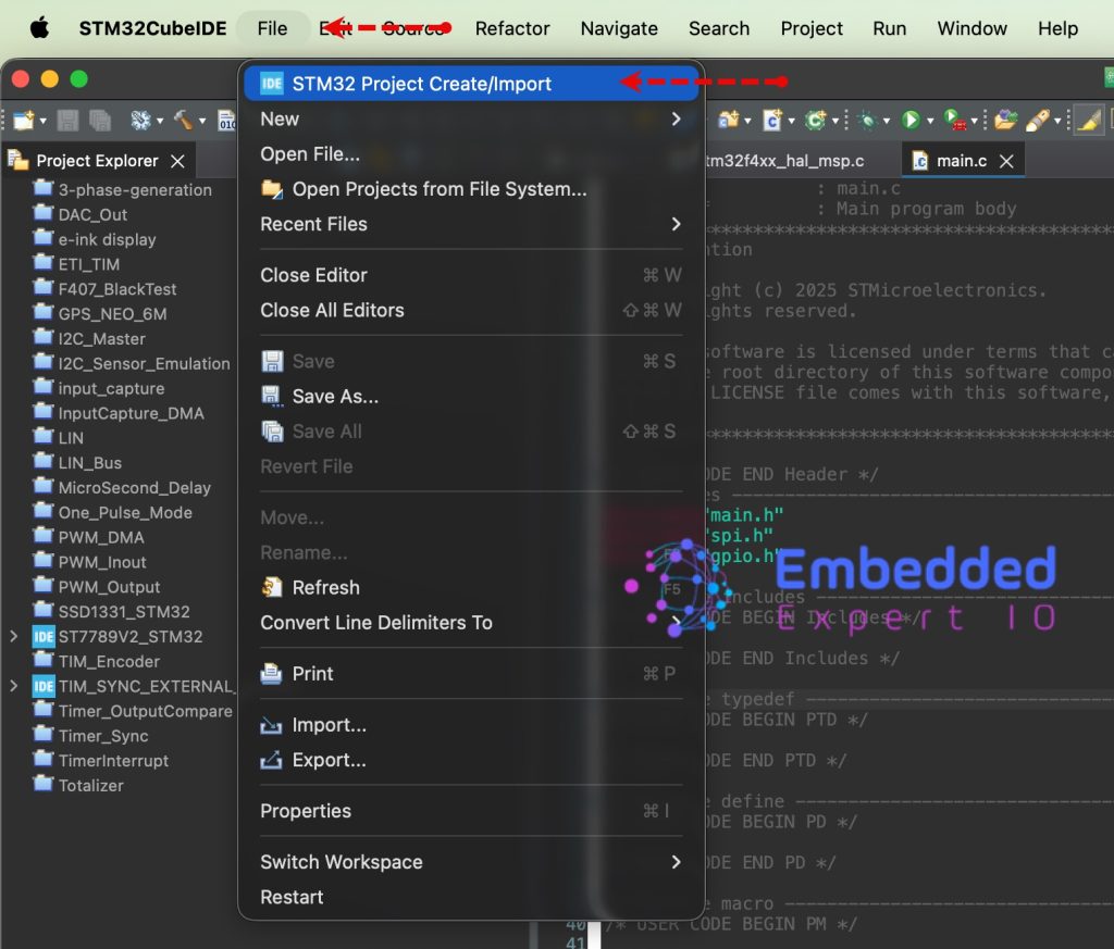
From the IDE, click File and select STM32 Project Create/Import as follows:
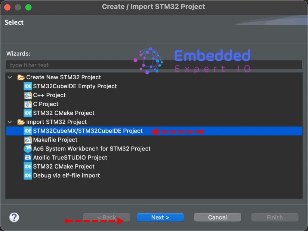
Next, from Import STM32 Project, select STM32CubeMX/STM32CubeIDE Project and click on Next as follows:
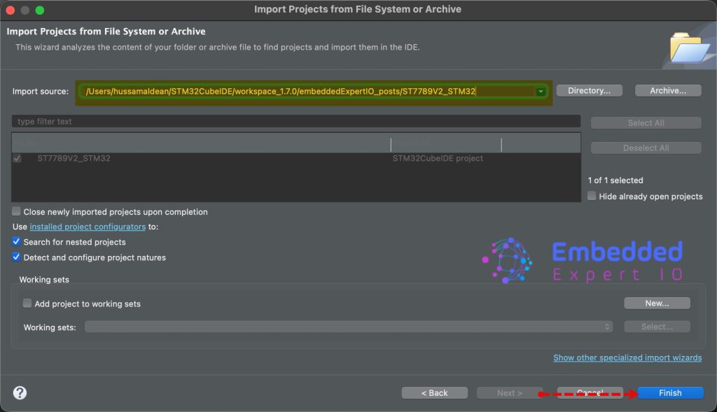
Next, select the folder that contains the .ioc file and click on Finish as follows:
Thats all for part 1.
Stay tuned for part 2 where we shall initialize the LCD and draw random colors to each pixel of the display.
Happy coding 😉
Add Comment