Using Timer1 as the external clock source for Timer2 on the STM32F4 allows Timer2 to advance strictly in response to Timer1’s output events, ensuring perfect hardware-level synchronization. This configuration is crucial in applications that demand phase-accurate timing chains, deterministic event propagation, or tightly coupled multi-timer control.
In this guide, we shall cover the following:
- Introduction.
- Theory.
- STM32CubeIDE setup.
- Firmware development.
- Results.
1. Introduction:
Synchronizing multiple timers is one of the most powerful but often under-explored capabilities of the STM32F4 timer architecture. When precise timing relationships are required—such as frequency tracking, deterministic event sequencing, or chained measurement and control loops—software-based coordination is never sufficient. Hardware-level synchronization ensures that timers operate in lockstep with cycle-accurate alignment, unaffected by interrupt latency, thread scheduling, or processor load. One of the most robust synchronization techniques available in the STM32F4 family is External Clock Mode 1, where one timer directly supplies clock pulses to another, effectively making the second timer advance strictly in response to the first.
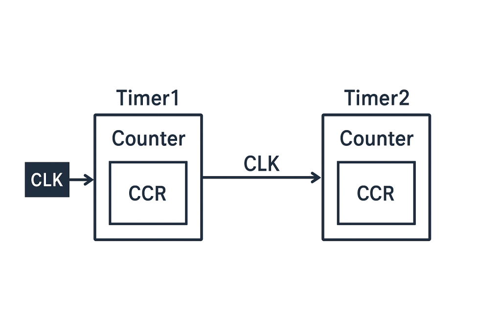
In this configuration, Timer1 acts as the master clock source, and Timer2 becomes the slave, counting only when Timer1 produces defined output events (such as update events or compare toggles). This transforms the internals of the microcontroller into a hardware-linked timing chain: Timer1 generates a pulse stream, and Timer2 uses these pulses as its external clock input. As a result, Timer2’s incrementing, overflow events, trigger outputs, and capture/compare operations become fully synchronized to Timer1’s timing domain. No PLL adjustments, interrupts, or software timers are involved; the relationship is established electrically inside the timer matrix.
This approach is particularly important when the system must maintain absolute deterministic timing, such as measuring derived frequencies, implementing cascaded counters, generating phase-aligned time bases, or coordinating complex multi-stage PWM systems. Because Timer2 only advances when Timer1 triggers it, any drift, jitter, or frequency variation in Timer1 automatically propagates to Timer2, preserving perfect temporal coherence. This is invaluable in high-precision measurement, motor control, power electronics, and instrumentation environments where logic must react to or track another timebase with exact fidelity.
By leveraging External Clock Mode 1 with Timer1 feeding Timer2, developers gain a powerful foundation for building synchronized timing subsystems that operate with hardware-level precision, immune to processor overhead and real-time operating system jitter. This method transforms the STM32F4 timers into truly synchronized digital timing blocks, enabling advanced applications that rely on tightly coupled and dynamically aligned timer behavior.
2. Theory:
Timer synchronization in the STM32F4 family allows multiple timers to operate in a coordinated, deterministic manner, enabling complex timing architectures that extend beyond the capabilities of a single timer. When using External Clock Mode 1, a timer no longer relies on the internal APB timer clock; instead, it increments in response to external signal transitions fed into its ETR (External Trigger) input. This transforms the timer into a hardware-based pulse counter, fully synchronized to an external timing domain.
In this configuration, TIM2 uses TIM1’s update events (or output compare toggles) as its external clock, meaning TIM2 increments only when TIM1 produces a clock pulse. This forms a master–slave structure in which TIM1 acts as the timing generator, and TIM2 behaves as a synchronized follower.
2.1. Concept of Master–Slave Timer Synchronization
STM32 timers feature flexible interconnection through internal trigger (ITR) signals. Each timer can output internal events—update events, compare events, or trigger outputs—that other timers can select as their clock or trigger source. When one timer (TIM1) is configured as the master and another (TIM2) as the slave, they operate in a fixed, hardware-defined relationship with:
- Deterministic timing
- Zero CPU overhead
- No interrupt latency
- Perfect cycle-to-cycle alignment
This hardware linkage ensures that any event produced by TIM1 is propagated directly to TIM2 through the microcontroller’s internal timer interconnect fabric.
2.2. External Clock Mode 1 Overview
External Clock Mode 1 allows a timer to use an external signal—not the internal clock—to drive its counter. For TIM2, the external clock can come from:
- A physical pin (ETR pin), or
- An internal trigger (ITR signal) from another timer
In your case:
- TIM1 generates a periodic signal (e.g., from OC toggle or update event)
- TIM2 selects TIM1’s signal as its ETR source (through internal routing)
- TIM2 increments on each rising/falling edge (depending on configuration)
Thus, TIM2 becomes a downstream counter fully synchronized to TIM1’s timing domain.
2.3. How the Synchronization Mechanism Works
2.3.1 TIM1 as the Master Clock Generator
TIM1 is configured to produce a signal at a precise rate, typically using:
- Output compare toggle mode
- PWM mode
- Update event pulses
These events are routed internally on the chip to one of the ITR lines connected to TIM2.
2.3.2 Routing Through ITR Lines
Each timer has several possible internal trigger inputs (ITR0, ITR1, ITR2, ITR3). The reference manual defines which timer maps to which ITR.
For STM32F4:
- TIM1 may map to ITR0 or ITR1
- TIM2 can select that ITR as its external clock source
This routing is purely internal, with zero propagation delay, and is not influenced by GPIO or external noise.
2.3.3 TIM2 Operating in External Clock Mode 1
TIM2 only increments on edges of the chosen trigger input.
Important behaviors:
- TIM2’s internal clock (from APB1) is ignored
- Only TIM1’s pulses dictate counting
- TIM2’s prescaler, auto-reload, and capture/compare still operate normally
TIM2 becomes a deterministic follower.
3. STM32CubeIDE Setup:
Open STM32CubeIDE after selecting the workspace and create new project as following:

Select the MCU:

Give the project a name:
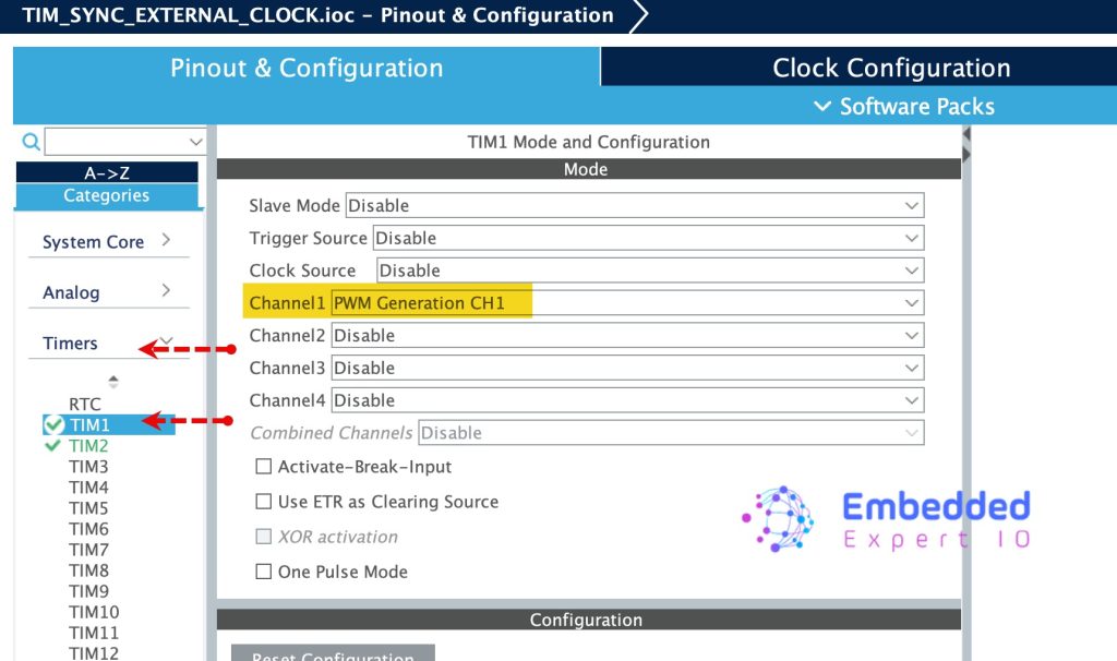
Next, Enable TIM1 since it will be the master as follows:
- Enable TIM1 and set Channel as PWM Generation.
Next, configure the timer as follows:
- Set prescaler to 16-1.
- Counter Period to 100-1.
- Trigger Event Selection to update event.
- From PWM Generation Channel 1, set Pulse to 40 (This will give duty cycle of 39).
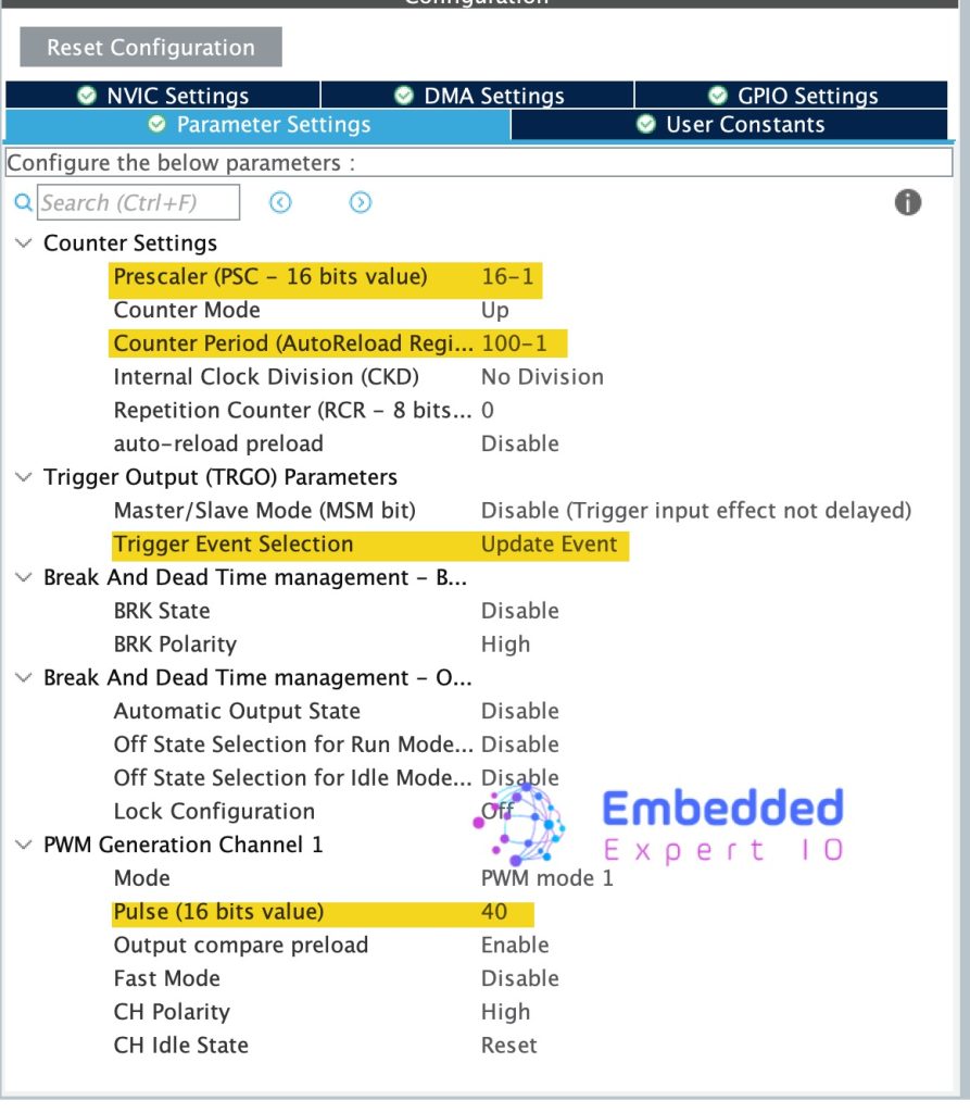
From the prescaler and counter period, since the bus connected to the timer is 16MHz, we will get 10KHz PWM frequency.
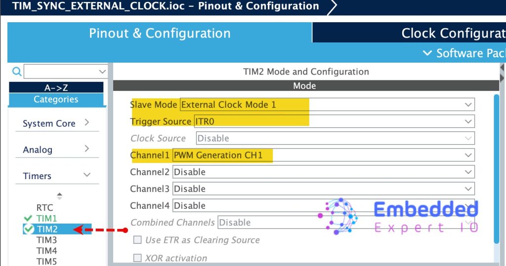
Next, enable TIM2 and set it as follows:
- Slave Mode to External Clock Mode 1
- Trigger Source ITR0.
- Channel 1 PWM Generation CH1.
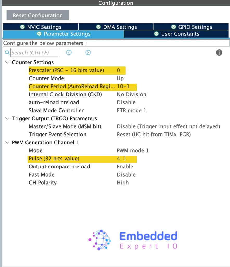
Configure TIM2 as follows:
- Set prescaler to 0.
- Set counter period to 10-1.
- Set Pulse width to 3 (This will give duty cycle of 30%)
With these setting, PA8 and PA0 will be enabled as TIM1_CH1 and TIM2_CH1 respectively.
That all for the configuration. Save the project and this will generate the code.
4. Firmware Development:
Once the code has been generated, main.c will be opened.
In user code begin 2 in main function, start the timers in PWM mode as follows:
  HAL_TIM_PWM_Start(&htim2, TIM_CHANNEL_1);
  HAL_TIM_PWM_Start(&htim1, TIM_CHANNEL_1);
That all for the firmware. Save, build and run the project.
4. Results:
By probing PA0 and PA8, yo should get the following:

The yellow trace for TIM1_CH1 and blue trace for TIM2_CH1.
The results confirm that the synchronization between TIM1 and TIM2 using External Clock Mode 1 is functioning exactly as intended. With TIM1 generating a 10 kHz clock signal and TIM2 configured with a period of 10 counts, the resulting 1 kHz output frequency from TIM2 aligns perfectly with theoretical expectations. This demonstrates the precision and reliability of hardware-based timer chaining on the STM32 platform, where event-driven synchronization ensures deterministic timing with zero software latency or jitter. Such behavior highlights the effectiveness of using a master-slave timer architecture when consistent frequency division, phase alignment, or multi-stage timing control is required.
Happy coding 😉
Add Comment