In this part, we dive into how the STM32 receives data from a 1-Wire sensor, interpreting the precise timing signals that represent logical bits. Understanding the reception phase is crucial, as it ensures accurate communication and reliable data retrieval from devices like the DS18B20 temperature sensor.
In this guide, we shall cover the following:
- STM32CubeIDE setup.
- Hardware connection.
- Firmware development.
- Results.
1. STM32CubeIDE Setup:
Open STM32CubeIDE after selecting the workspace and create new project as following:

Select the MCU:

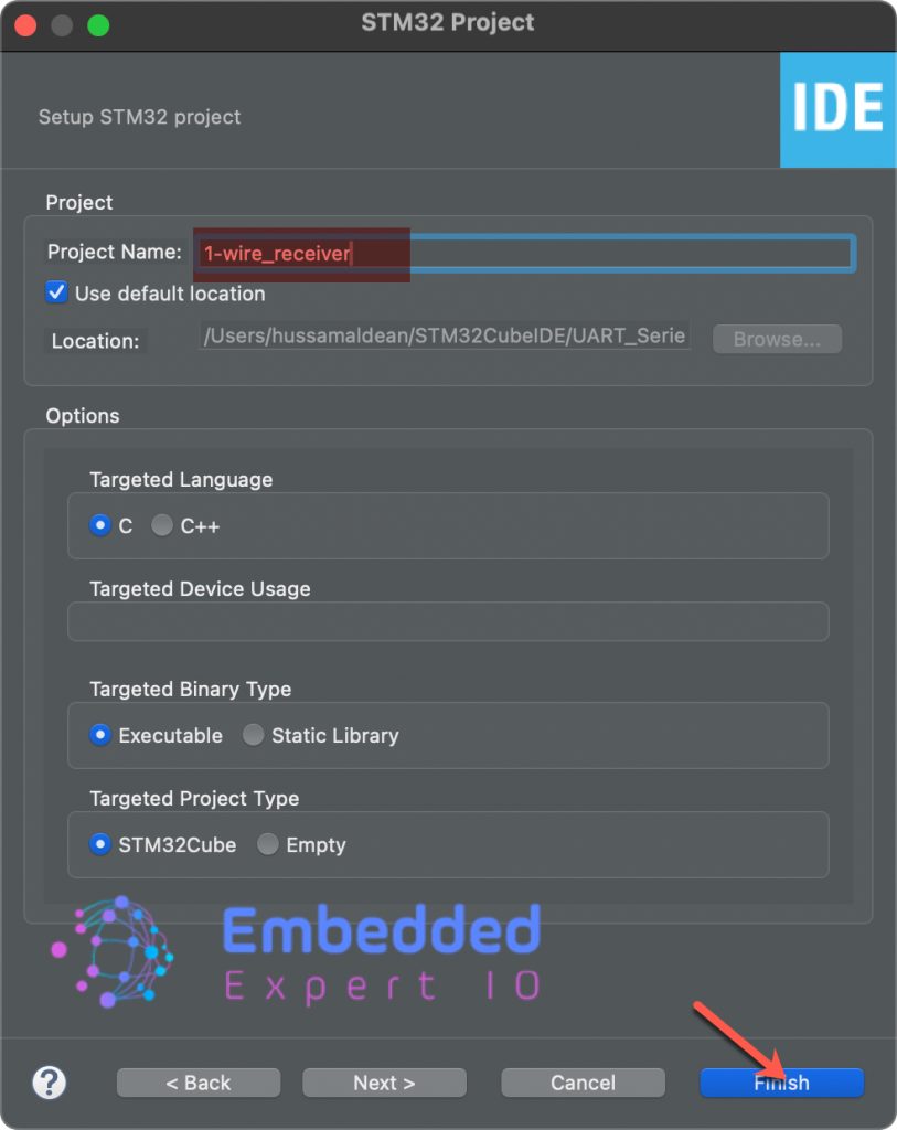
Give the project a name and click on finish:
Once the project has been created, STM32CubeMX shall appear.
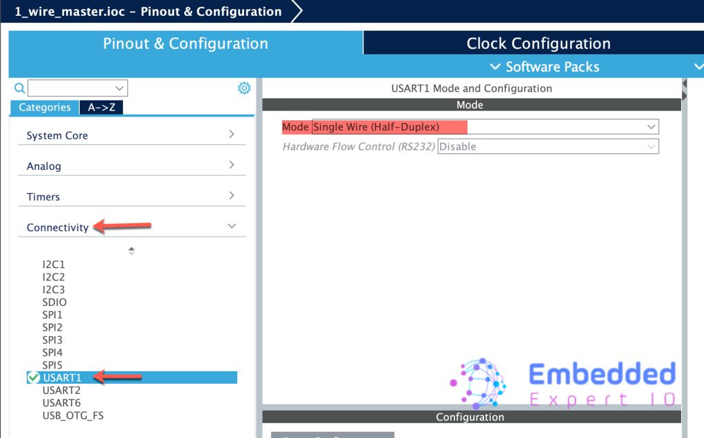
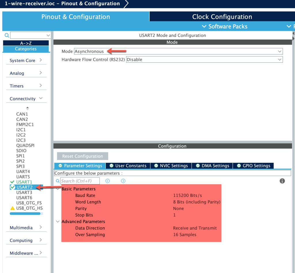
From connectivity, select USART1 (Or any other serial you want) and set the mode as Single-Wire (Half-duplex) as follows:
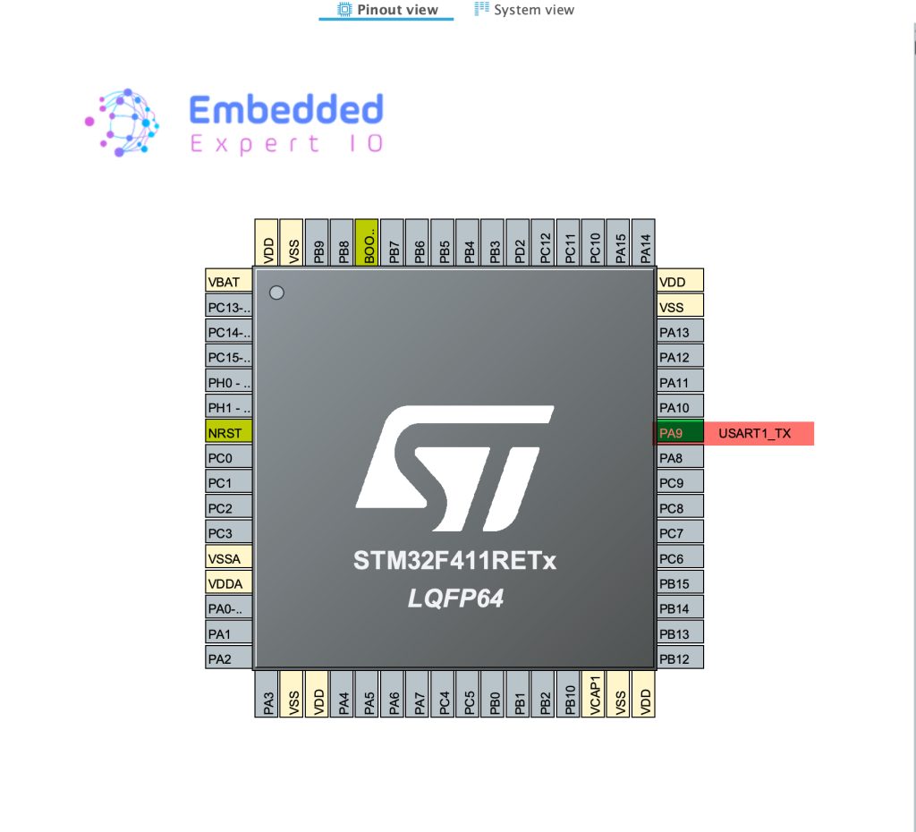
This wil set PA9 as UART1_TX pin as follows:
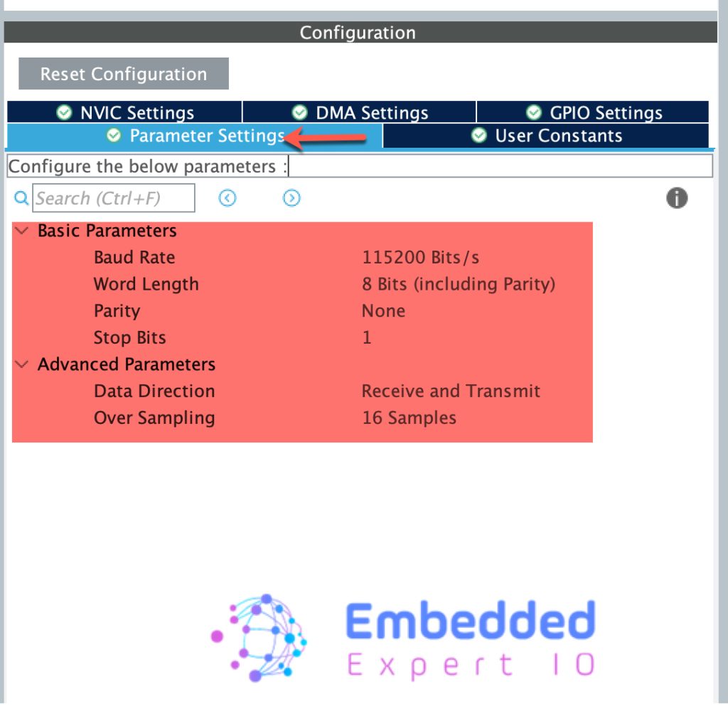
In the configuration, leave everything as is:
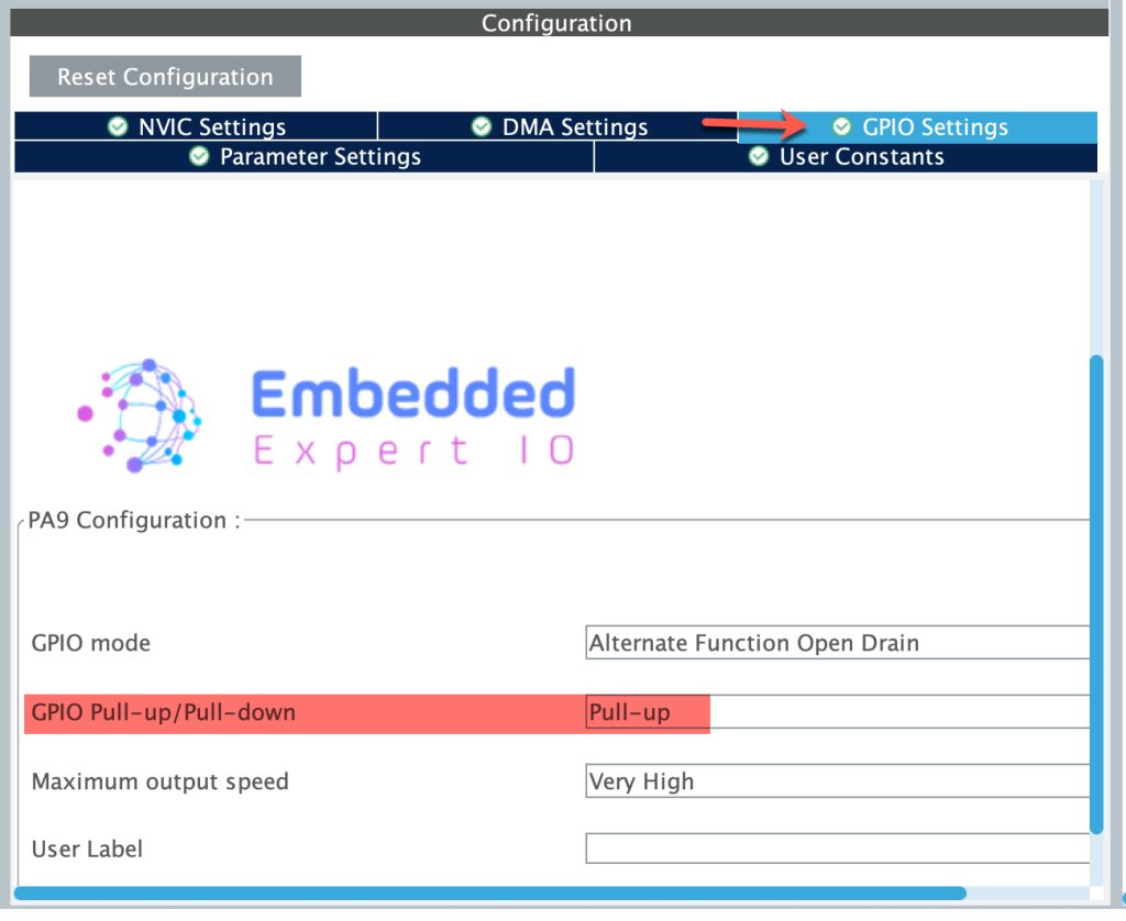
Next, from GPIO Settings, enable the Pullup resistor as follows:
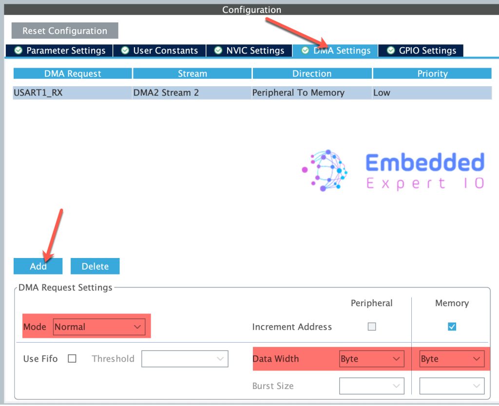
Next, from DMA settings, add DMA stream as follows:
- Mode to Normal.
- Data width is byte for peripheral and memory.
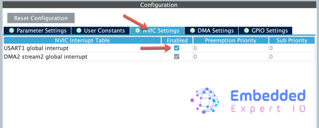
Next, from NVIC, enable USART1 global interrupt as follows:
Next, enable USART2 which will allow us to on board ST-Link VCOM to print the received data as follows:
- Keep the configuration as is.
Thats all for the configuration. Save the project and this will generate the code.
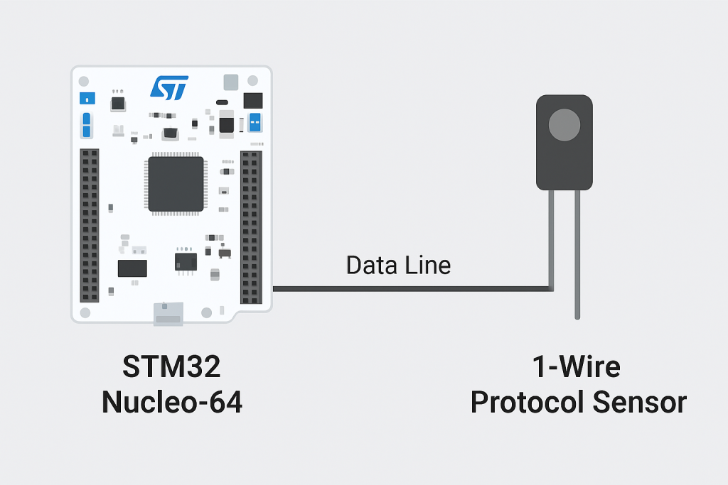
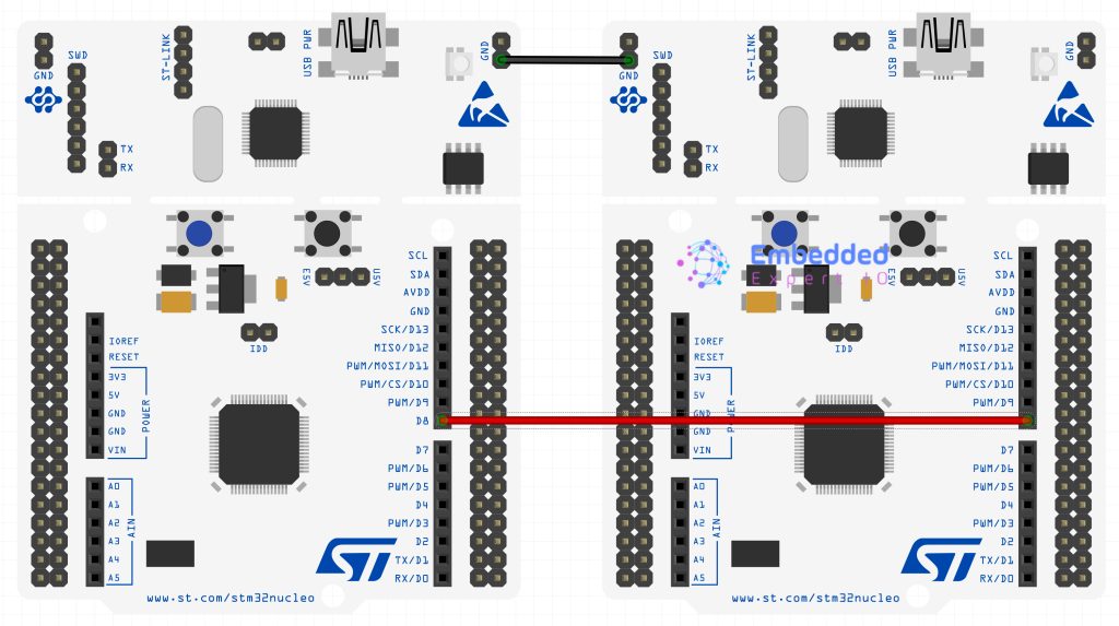
2. Connection:
The connection as follows:
- Connect PA9 of sender to PA9 of the receiver.
- Connect GND of first MCU to the GND of the second MCU.
3. Firmware Development:
Once the code has been generated, main.c shall be opened.
In main.c, in user begin PV section, declare the following:
#define BufferSize 100

uint8_t uart_buffer[BufferSize];
This will be the buffer to hold the received data from UART in 1 wire mode.
Next, in user code begin 2 in main function, set the UART in the reception mode as follows:
HAL_HalfDuplex_EnableReceiver(&huart1);
Next, start the reception of the data using DMA and detect the end of the message using IDLE line as follows:
HAL_UARTEx_ReceiveToIdle_DMA(&huart1, uart_buffer, BufferSize);
This function will call the following function under two conditions:
- The UART received 100 characters.
- IDLE line has been detected.
Once one of the conditions have been met, the following function shall be called:
void HAL_UARTEx_RxEventCallback(UART_HandleTypeDef *huart, uint16_t Size)
{
	if(huart->Instance==USART1)
	{
		HAL_UART_Transmit(&huart2, uart_buffer, Size, 100);
		HAL_UARTEx_ReceiveToIdle_IT(&huart1, uart_buffer, 30);
	}
}
For more information about this method, please refer to this guide here.
For how to transmit data, please refer to this guide here.
Thats all for the reception. Build the project and run it.
4. Results:
After following the connection, open your favourite terminal application, set the baud rate to 115200, you should get the following:
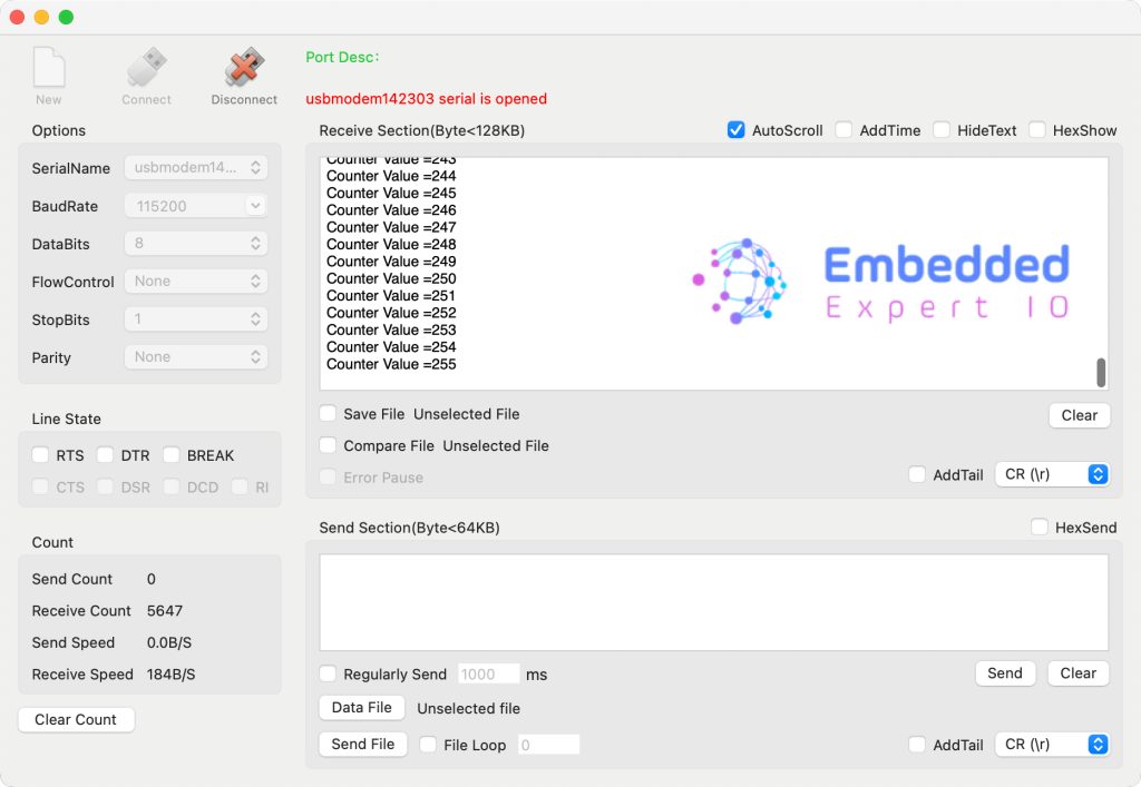
We have successfully received data from another MCU using 1-wire. Next, we shall communicate with 1-wire enabled sensor.
Stay tuned.
Happy coding 😉
Add Comment