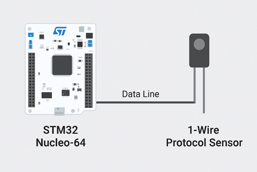
The 1-Wire protocol is a simple, low-speed communication standard developed by Dallas Semiconductor (Maxim) that uses just a single data line and ground for both power and data exchange. It enables multiple devices, such as sensors and memory chips, to share the same bus, making it ideal for cost-sensitive and space-constrained applications.
In this guide, we shall cover the following:
- What is 1-wire protocol.
- STM32CubeMX setup.
- Transmit firmware development.
- Results.
1. What is 1-Wire Protocol:
The 1-Wire protocol is a communication standard originally developed by Dallas Semiconductor (now Maxim Integrated) that allows data transfer between a microcontroller and peripheral devices using just a single data line plus ground. Unlike protocols such as I²C or SPI that require multiple lines for clock and data, 1-Wire is unique in its simplicity, enabling bidirectional communication through one shared wire. This makes it highly appealing for cost-sensitive, compact, or resource-constrained applications.
A defining feature of the 1-Wire bus is its ability to support multiple devices on the same line. Each device connected to the bus carries a unique 64-bit serial code programmed at the factory. This guarantees that even if many sensors are connected to the same bus, the master (for example, an STM32 microcontroller) can uniquely identify, address, and communicate with each device individually. This capability makes 1-Wire particularly powerful in distributed sensing applications, such as large sensor networks for temperature, humidity, or identification systems.
Another key advantage is the option of parasitic power mode, where devices can operate by drawing power directly from the data line. This eliminates the need for a dedicated power supply pin, further reducing wiring complexity. While the data rate is relatively low compared to faster buses like SPI, the reduction in wiring and simplicity of design often outweigh the speed limitation in use cases where only small amounts of data need to be exchanged.
From the perspective of STM32 microcontrollers, integrating a 1-Wire sensor typically involves using a standard GPIO pin to emulate the timing requirements of the protocol. The protocol relies heavily on precise timing sequences to differentiate between logical “1” and “0,” as well as to issue reset and presence pulses during initialization. While software bit-banging is commonly used, some STM32 families allow leveraging features like timers or UART configured in half-duplex mode to implement 1-Wire more efficiently.
One of the most well-known 1-Wire devices is the DS18B20 digital temperature sensor, which has been widely adopted across industries. It can provide accurate temperature readings, support multiple devices on the same bus, and operate in harsh environments. Beyond temperature sensors, the 1-Wire ecosystem also includes memory devices, authentication ICs, and iButtons used for identification and access control.
When comparing 1-Wire to other protocols, it becomes clear that its strength lies not in speed but in scalability and simplicity. In applications where wiring cost, pin count, or physical space is critical, 1-Wire offers a practical and elegant solution. Furthermore, because each device has a globally unique identifier, there is no need for address assignment, reducing configuration overhead.
In modern embedded systems, where microcontrollers like STM32 are often connected to numerous peripherals, the 1-Wire protocol fills a special niche. It is ideal for applications such as environmental monitoring, smart home devices, energy meters, and portable systems where simplicity and reliability are more important than raw speed.
In summary, 1-Wire sensors combine minimal hardware requirements, unique device identification, and flexibility in powering options, making them a versatile choice for embedded engineers. By mastering the protocol and its integration with STM32, developers can efficiently design systems that are compact, scalable, and robust while maintaining low cost and wiring complexity.
2. STM32CubeMX Configuration:
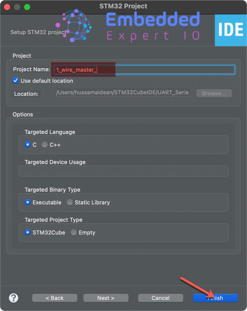
Open STM32CubeIDE after selecting the workspace and create new project as following:

Select the MCU:

Give the project a name and click on finish:
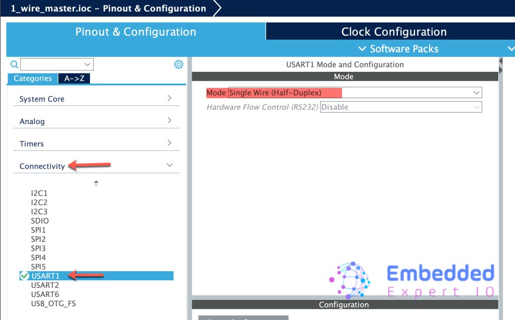
Once the project has been created, STM32CubeMX shall appear.
From connectivity, select USART1 (Or any other serial you want) and set the mode as Single-Wire (Half-duplex) as follows:
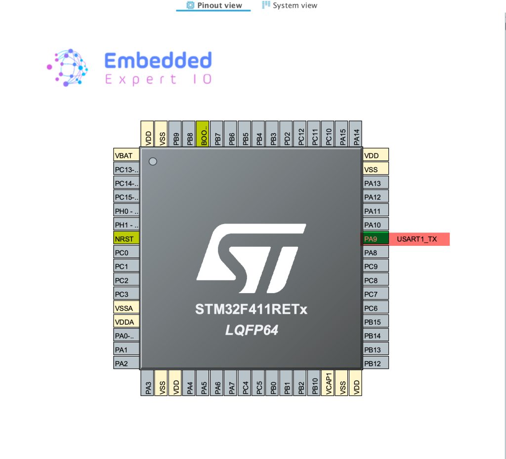
This wil set PA9 as UART1_TX pin as follows:
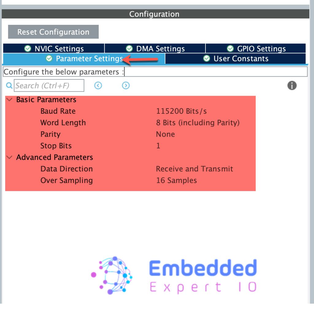
In the configuration, leave everything as is:
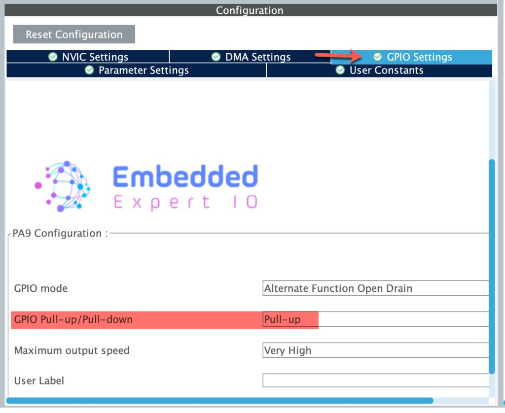
Next, from GPIO Settings, enable the Pullup resistor as follows:
Thats all for the configuration. Save the project and this will generate the project.
3. Transmit Firmware Development:
Once the project is generated, main.c will be opened.
In main.c in user begin includes, include stdio as follows:
#include "stdio.h"
Next, in user code begin PV:
Declare counter variable to hold the counted value as follows:
uint8_t counter;
Next, declare the buffer to hold the data to be transmitted as follows:
uint8_t buffer[100];
Next, in user code begin 3 in while 1 loop:
int len = sprintf((char*)buffer, "Counter Value =%d\n", counter);
This will convert the string to character array and return how many characters has been used and store the length in len variable.
Next, change the direction from receiving to transmit as follows:
HAL_HalfDuplex_EnableTransmitter(&huart1);
Transmit the data:
HAL_UART_Transmit(&huart1, buffer,len,1000);
Which is similar to part 1 of the guide.
Once the transfer is completed, put the UART into reception mode as follows:
HAL_HalfDuplex_EnableReceiver(&huart1);
Increment the counter as follows:
counter++;
Delay by 100ms:
HAL_Delay(100);
Thats all for the firmware.
Build the project and run it.
4. Results:
By connecting logic probe to pin PA9 (D8 of Arduino connector):
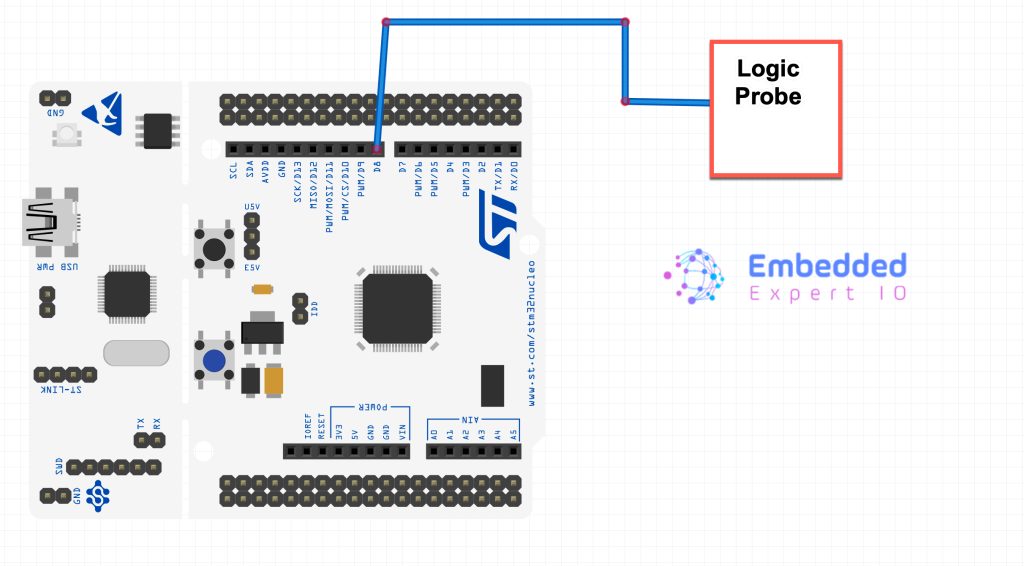
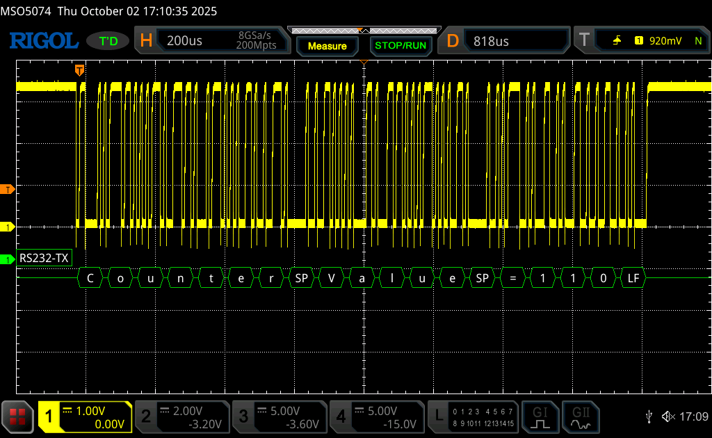
You should get the following:
Next, we shall use interrupt to receive data.
Stay tuned.
Happy coding 😉
Add Comment