In this fourth part of the guide, we move beyond simple responses and begin building a basic web user interface that runs directly from the STM32. The web assets will be hosted by the Mongoose HTTP server, demonstrating how embedded devices can provide interactive configuration and monitoring through a browser.
In this guide, we shall cover the following:
- Creating the web UI.
- Integrate the web UI into the project.
- Firmware development.
- Results.
1. Creating the Web UI:
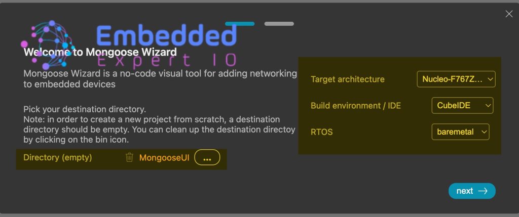
First, head to this website called mongoose wizard from here.
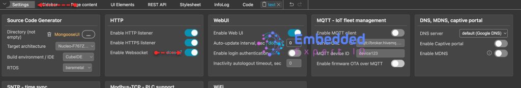
Next, select the directory and make sure it is empty.
Also, set the target architecture to be STM32 (I’ve selected F767 Nucleo), IDE to STM32CubeIDE and bare metal. We are not interested to use RTOS in this guide.
Click on next
Next, select LED toggle and click on next as follows:
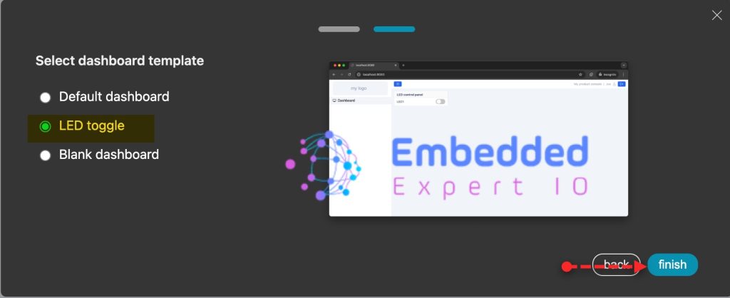
The UI wizard shall be opened.
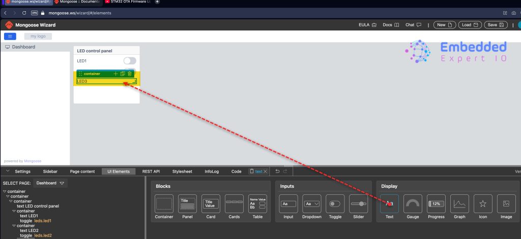
Next, add a container to the LED Control Panel as follows:
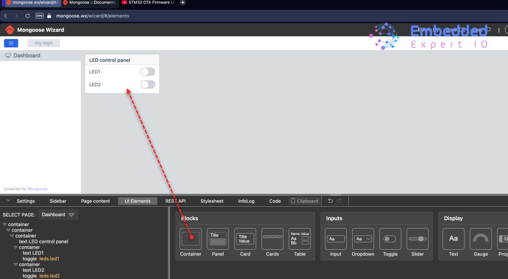
Add Text and set it to LED3 as follows:
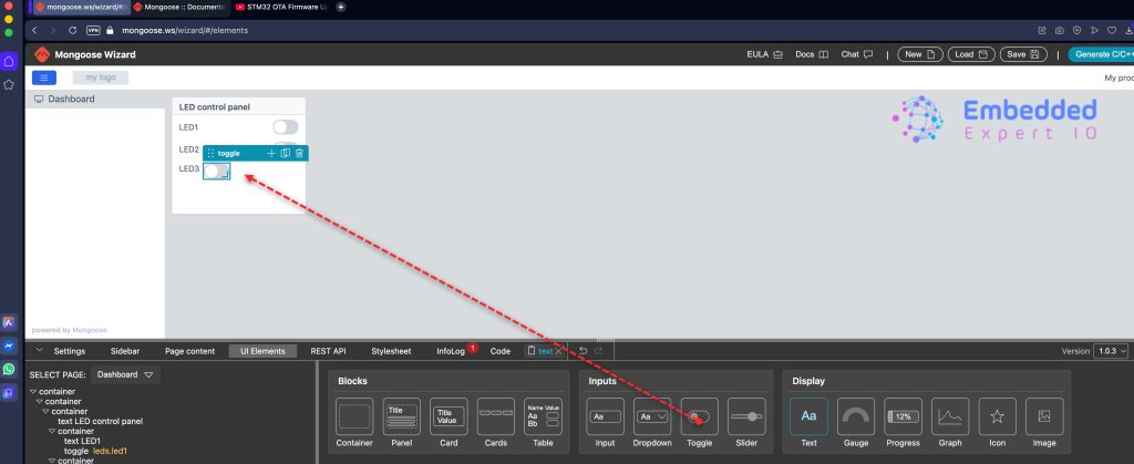
Next, add Toggle button as follows:
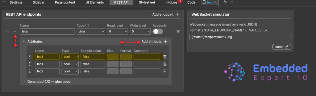
Next, from REST API, expand leds endpoint and add the following attribute as follows:
- Name to led3
- Type to bool.
- Sample Value to false.
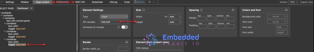
From Page content, select toggle for LED3 and set API variable to leds.led3 as follows:
Next, add a container next to LED control panel and add Panel as follows:
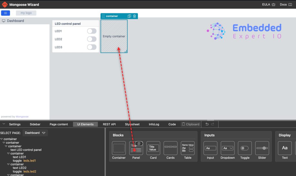
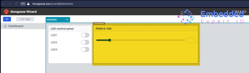
Delete the content of the panel and name to PWM 0-100 and add slider as follows:
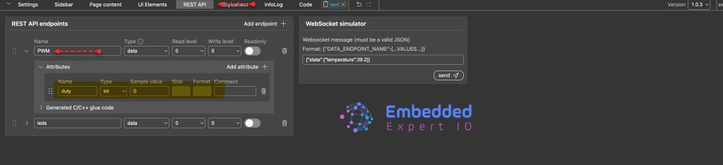
Next, from REST API, create a new end points with the following parameters:
- Name is PWM
For Attributes:
- Attribute Name to PWM.
- Type to int.
- Sample value to any value (0 in this case).
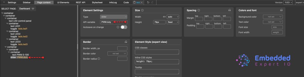
Next, from Page content select the slider and set the API variable to PWM.duty as follows:
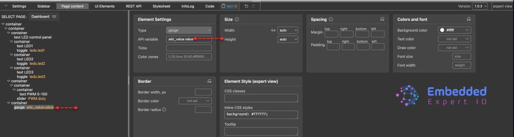
Next, add new container and add a gauge as follows:
Here, I set the background to white.
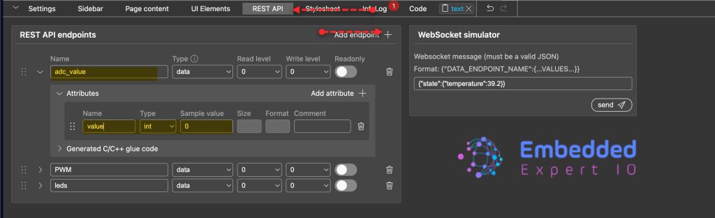
Create new REST API with the following:
- Name as adc_value.
Attributes:
- Name as value.
- Type to int.
- Sample value to 0.
Next, from Page content, select gauge and set API variable to adc_value.value as follows:
Next, from Settings, enable Websocket as follows:
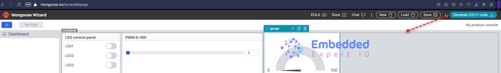
That all for the UI, click on generate C/C++ code as follows:
2. Integrate theWeb UI Into the Project:
First take a copy of the older project.
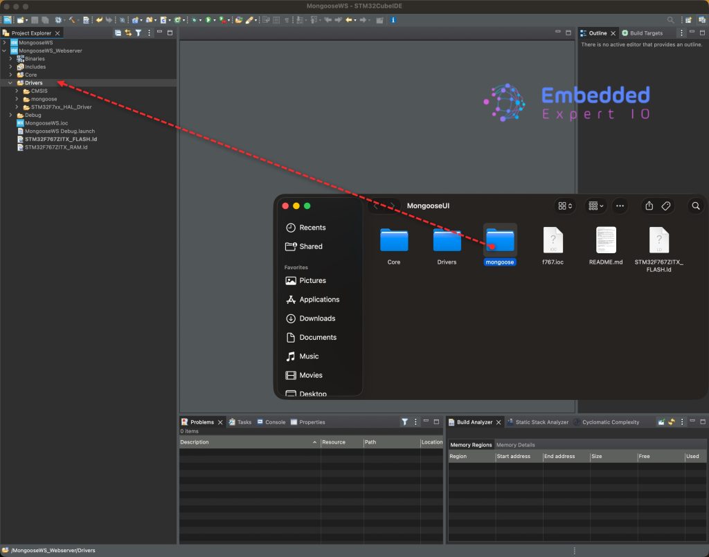
Open the generated project and copy the mongoose to the driver folder as follows:
Next, make sure to delete the mongoose related files in Core/inc and Core/src.
Please note that you need to copy the content of mongoose_config.h from the older version into the new generated mongoose config header which is located in mongoose folder.
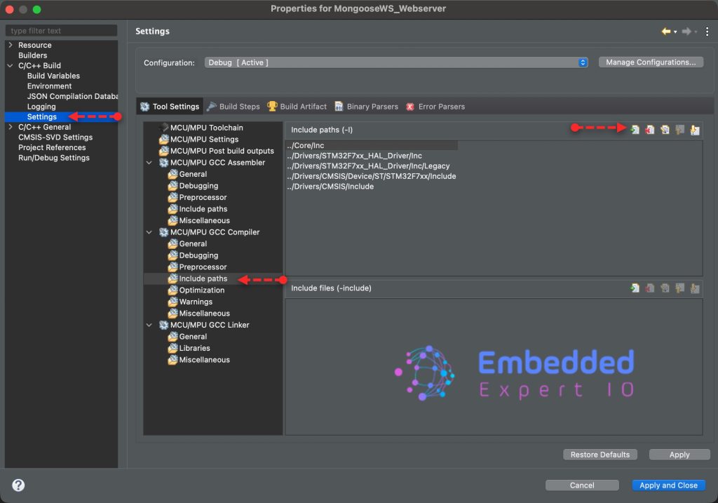
Next, right click on the project and click on properties.
Go to settings, MCU/MPU GCC complier and click add in include paths as follows:
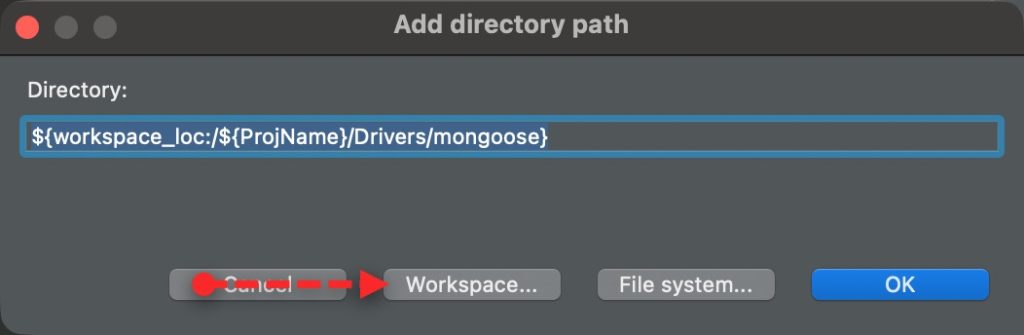
Select Workspace and add mongoose folder as follows:
Click on OK then Apply and close.
Thats all for the integration of the web server.
3. Firmware Development:
In main.c file, in user code begin includes include the following header file:
#include "mongoose_glue.h"
Note: remove the old mongoose.h inclusion, it is no longer needed.
Since we shall use websocket, we need a handler for the websocket. In user code begin 0 declare the following function:
static void my_getter(struct real_time_data *data)
{
	//TODO
}
This will be handler in part 5.
In user code begin 2 in main function:
Initialize the mongoose as follows:
mongoose_init();
Start the http handler and ws responder as follows:
  mongoose_set_http_handlers("real_time_data", my_getter, NULL);
  mongoose_add_ws_reporter(200, "real_time_data");
In user code begin 3 in while 1 loop:
mongoose_poll();
Thats all for the firmware.
Save, build and run the project as follows:

4. Results:
Connect the your board to the router and type the address of the board into the browser.
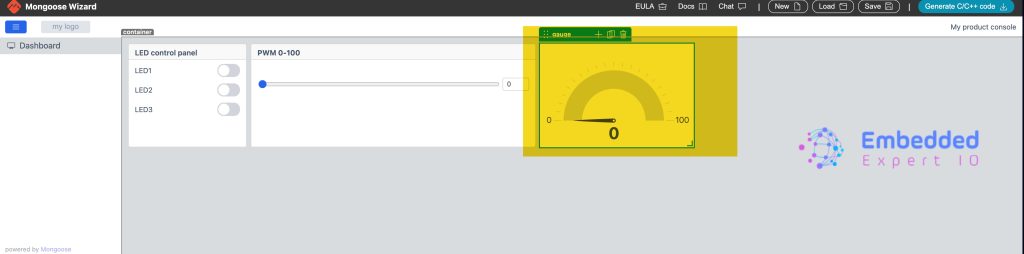
You will get the following:
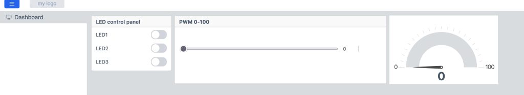
In next part, we shall connect the UI to the peripherals like LEDs and ADC.
Stay tuned.
Happy coding 😉
Add Comment