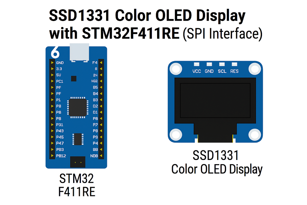
In this guide, we will focus on the firmware side by initializing the SSD1331 controller and preparing it for operation. Once initialized, we’ll implement a simple routine to draw a single pixel on the OLED display as the foundation for more complex graphics.
In this guide, we shall cover the following:
- Initialization of the display.
- Main Firmware.
- Results.
5. Initialization of the Display:
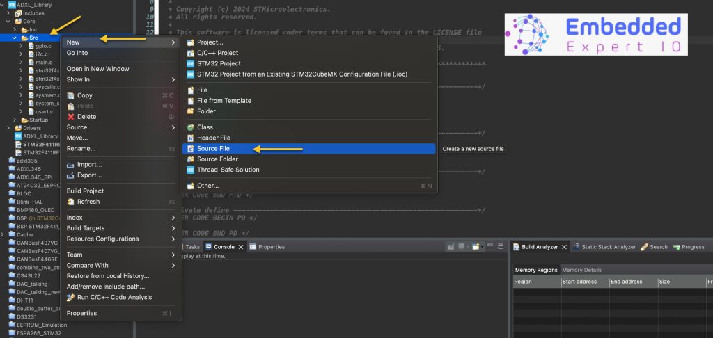
We start by creating new source and header file with name of ssd1331.c and ssd1331.h respectively.
Right click on Src folder and add new source file as following:
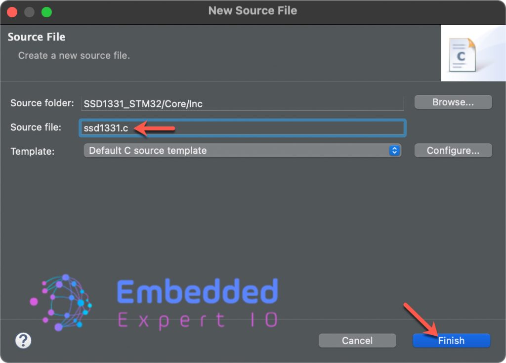
Give a name for the source file, we shall name it as ssd1331.c as following:
In similar manner, right click on Inc folder and add new header file with name of ssd1331.h.
Next, open ssd1331.h header file and include the following header files:
#include "main.h"
#include "spi.h"
These headers files will enable us access to SPI functions and the symbolics names of the GPIO.
Next, declare the size of the display as follows:
#define SSD1331_WIDTH   96
#define SSD1331_HEIGHT  64
Next, declare the following two functions:
void ssd1331_init(void);
void ssd1331_drawPixel(uint8_t x, uint8_t y, uint16_t color);
First function to initialize the OLED display.
The second one to draw a single pixel.
Thats all for the header file.
Next, open ssd1331.c file.
Within the source file, include ssd1331 header file as follows:
#include "ssd1331.h"
Next, static functions for setting the state of the reset pin as follows:
static void RST_LOW(void)
{
	HAL_GPIO_WritePin(RES_GPIO_Port, RES_Pin, GPIO_PIN_RESET);
}

static void RST_HIGH(void)
{
	HAL_GPIO_WritePin(RES_GPIO_Port, RES_Pin, GPIO_PIN_SET);
}
Once the reset pin is set to low, the ssd1331 shall reset itself and remain in the reset state until the reset pin is set back to high.
Next, function to select and deselect the ssd1331 display as follows:
static void SSD_Deselect(void)
{
	HAL_GPIO_WritePin(CS_GPIO_Port, CS_Pin, GPIO_PIN_SET);
}

static void SSD_Select(void)
{
	HAL_GPIO_WritePin(CS_GPIO_Port, CS_Pin, GPIO_PIN_RESET);
}
The ssd1331 follows the conventional chip select for any SPI peripheral, when CS pin is low, the ssd1331 will accept data from the SPI bus and won’t accept data from SPI bus when CS pin is high.
Next, a function to write a command to the display as follows:
static void ssd1331_command(uint8_t cmd)
{
    HAL_GPIO_WritePin(DC_GPIO_Port, DC_Pin, GPIO_PIN_RESET); // DC = 0
    SSD_Select();
    HAL_SPI_Transmit(&hspi1, &cmd, 1, HAL_MAX_DELAY);
    SSD_Deselect();
}
When the DC pin is set to low, the ssd1331 shall treat the data as command and configure its internal registers.
Next, we need to transmit data buffer as follows:
static void ssd1331_data_buffer(uint8_t *data, size_t len)
{
    HAL_GPIO_WritePin(DC_GPIO_Port, DC_Pin, GPIO_PIN_SET); // DC = 1
    SSD_Select();
    HAL_SPI_Transmit(&hspi1, data, len, HAL_MAX_DELAY);
    SSD_Deselect();
}
When DC pin is set to high, the ssd1331 will treat the data as pixel data. This will be necessary when draw a pixel later.
Next, ssd1331 initialization.
Start by declaring the initialization sequence function:
void ssd1331_init(void)
Within the function:
Reset the display:
RST_LOW();
HAL_Delay(10);
RST_HIGH();
HAL_Delay(50);
Next Initialize the display:
// Initialization sequence
ssd1331_command(0xAE);              // Display off
ssd1331_command(0xA0); ssd1331_command(0x72); // Set Remap & Color Depth
ssd1331_command(0xA1); ssd1331_command(0x00); // Set Display Start Line
ssd1331_command(0xA2); ssd1331_command(0x00); // Set Display Offset
ssd1331_command(0xA4);              // Normal Display (not all-on)
ssd1331_command(0xA8); ssd1331_command(0x3F); // Set Multiplex Ratio
ssd1331_command(0xAD); ssd1331_command(0x8E); // Master Config
ssd1331_command(0xB0); ssd1331_command(0x0B); // Power Save Mode
ssd1331_command(0xB1); ssd1331_command(0x31); // Phase Period Adjust
ssd1331_command(0xB3); ssd1331_command(0xF0); // Clock Divider / Oscillator
ssd1331_command(0x8A); ssd1331_command(0x64); // Precharge A
ssd1331_command(0x8B); ssd1331_command(0x78); // Precharge B
ssd1331_command(0x8C); ssd1331_command(0x64); // Precharge C
ssd1331_command(0xBB); ssd1331_command(0x3A); // Precharge Level
ssd1331_command(0xBE); ssd1331_command(0x3E); // VCOMH
ssd1331_command(0x87); ssd1331_command(0x06); // Master Current
ssd1331_command(0x81); ssd1331_command(0x91); // Contrast A
ssd1331_command(0x82); ssd1331_command(0x50); // Contrast B
ssd1331_command(0x83); ssd1331_command(0x7D); // Contrast C
ssd1331_command(0xAF);              // Display ON
These has been taken from adafruit library.
Next, draw pixel function:
void ssd1331_drawPixel(uint8_t x, uint8_t y, uint16_t color)
{
    if (x >= SSD1331_WIDTH || y >= SSD1331_HEIGHT) return; // Out of bounds

    // Set column
    ssd1331_command(0x15);
    ssd1331_command(x);
    ssd1331_command(x);

    // Set row
    ssd1331_command(0x75);
    ssd1331_command(y);
    ssd1331_command(y);

    // Send pixel color (RGB565)
    uint8_t data_buf[2] = {
        (uint8_t)(color >> 8),
        (uint8_t)(color & 0xFF)
    };
    ssd1331_data_buffer(data_buf, 2);
}
The function draws one pixel on the SSD1331 OLED at coordinates (x, y) with a 16-bit RGB565 color.
- Bounds check
The function first checks ifxoryis outside the valid display area (SSD1331_WIDTH = 96,SSD1331_HEIGHT = 64). If the pixel is out of range, it simply returns without doing anything. - Set column address
It sends command0x15(SET COLUMN).- The next two bytes define the start and end column.
- Both are set to
x, so the address window spans exactly one column.
- Set row address
It sends command0x75(SET ROW).- The next two bytes define the start and end row.
- Both are set to
y, so the address window spans exactly one row.
(x, y). - Send color data
Thecolorparameter is a 16-bit RGB565 value (5 bits red, 6 bits green, 5 bits blue).- The function splits it into a high byte and a low byte.
- Both bytes are sent as data (not commands) to the display.
(x, y)with the chosen color.
Thats all for the source file. Save it.
6. Main Firmware:
Open main.c.
Within main.c in user code begin includes, include the following header files:
#include "ssd1331.h"

#include "stdlib.h"
The stdlib will allow us to use random function.
In user code begin 2 in main function:
ssd1331_init();
In user code begin 3 in we shall fill the display with random colors for each pixels as follows:
for(int i=0;i<SSD1331_HEIGHT;i++)
{
  for (int j=0;j<SSD1331_WIDTH;j++)
  {
    ssd1331_drawPixel(j,i,rand() % 65535);


  }
}

HAL_Delay(1000);
Save the project, build it and run it on your board as following:

7. Results:
Next, we shall use more efficient way to draw picture etc.
Stay tuned.
Happy coding 😉
Add Comment