This guide provides a concise introduction to getting started with the dual-core STM32H747 MCU, focusing on project creation, core-specific GPIO configuration, and firmware flashing. It explains the fundamental steps required to correctly assign resources to each core and program both cores reliably.
In this guide, we shall cover the following:
- STM32CubeMX project creation.
- Importing project STM32CubeIDE to STM32CubeIDE.
- Firmware Development.
- Project configuration.
- Results.
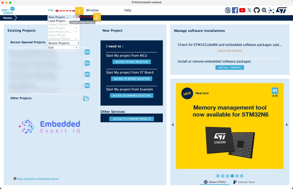
1. STM32CubeMX Project Creation:
Open STM32CubeMX as start a new project as follows:
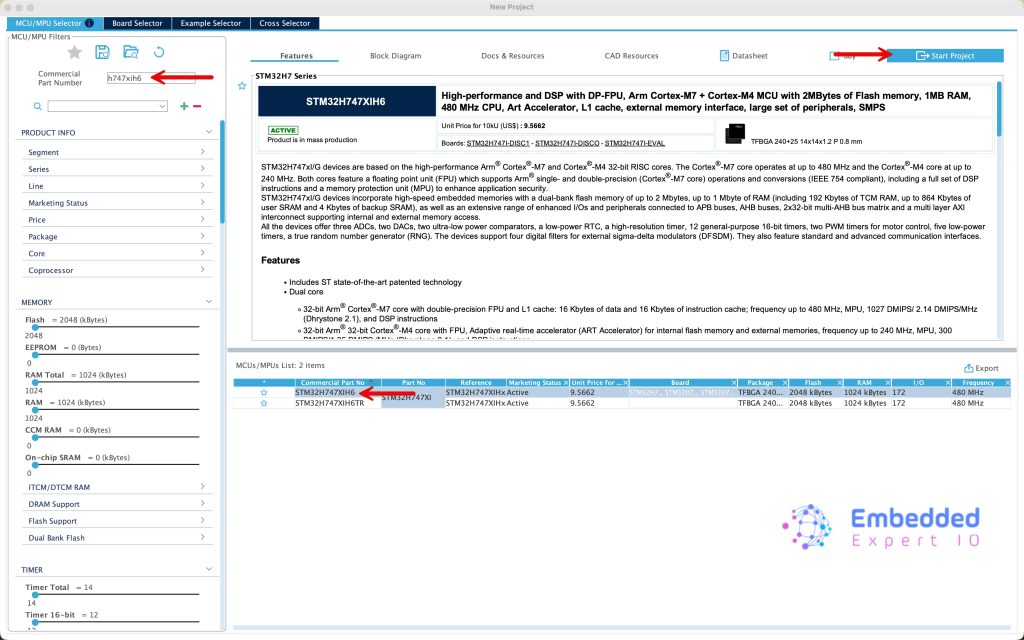
Search for your STM32 MCU, select the MCU and click on Start New Project as follows:
It will ask to configure the MPU, click on Yes as follows:

Since this guide uses STM32H747XI in Arduino Giga R1 WiFi, we shall use the onboard LEDS to be controlled by each core.
From the schematic of the board, we find the following:
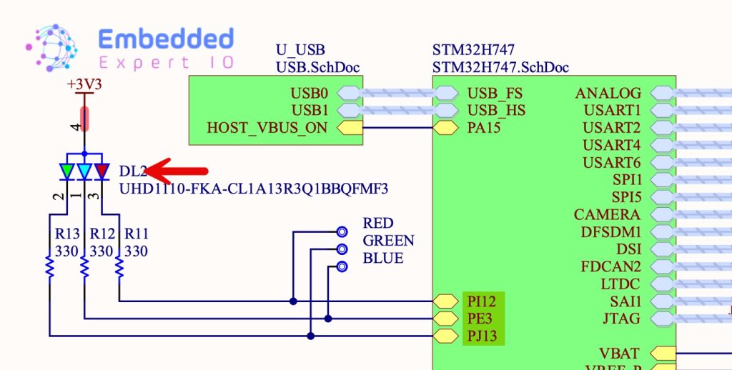
| LED Color | Pin |
| Red | PI12 |
| Blue | PE3 |
| Green | PJ13 |
In this guide, we shall use the red and blue LED.
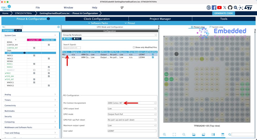
Set PE3 as output and give it a name of LEDM7 which will be configured for Cortex M7.
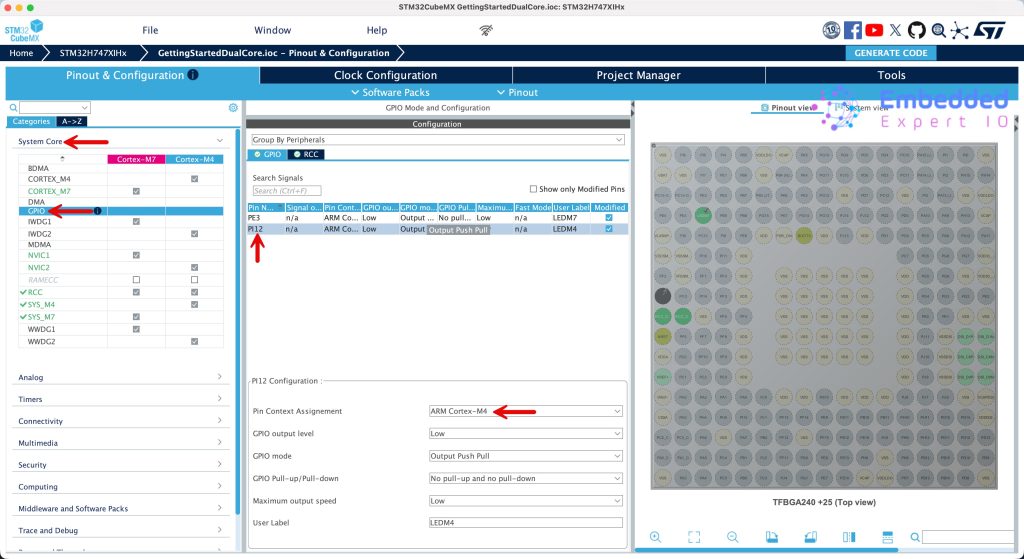
Set PI12 as output and give it a name of LEDM4 which will be configured for Cortex M4.
Next, from system core, select GPIO and assign PI12 (Blue LED) to Cortex M4 as follows:
In similar manner, assign PE3 to Cortex M7 as follows:
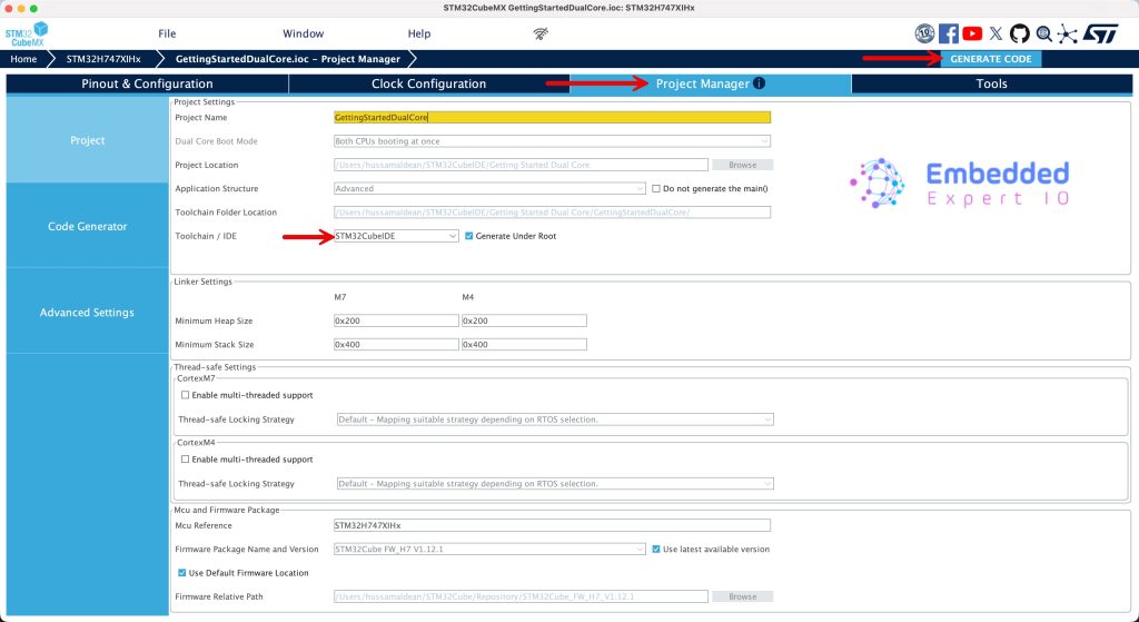
Next, From Project Manager, give the project a name and set the toolchain/IDE as STM32CubeIDE and click on generate as follows:
2. Importing the Project to STM32CubeIDE:
Open STM32CubeIDE, select your workspace and click on Launch.
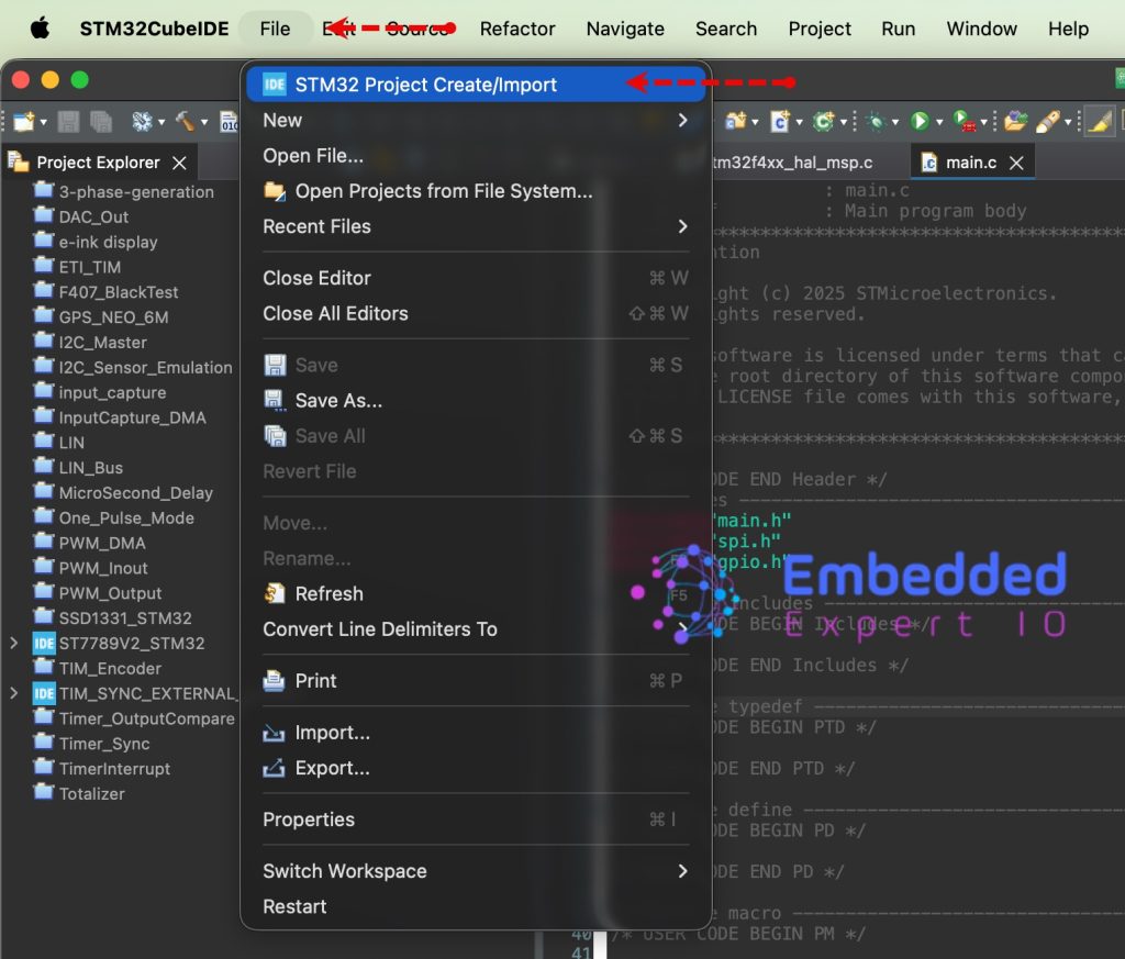
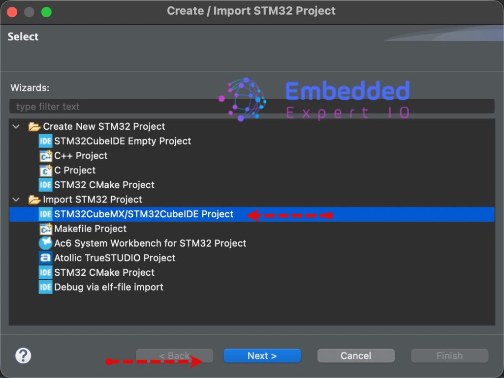
From the IDE, click File and select STM32 Project Create/Import as follows:
Next, from Import STM32 Project, select STM32CubeMX/STM32CubeIDE Project and click on Next as follows:
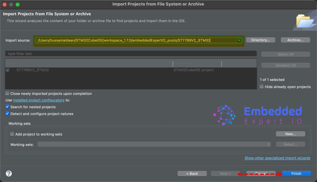
Next, select the folder that contains the .ioc file and click on Finish as follows:
3. Firmware Development:
Once the project has been imported, you will notice there is two project, one for CM4 and the other for CM7 as follows:
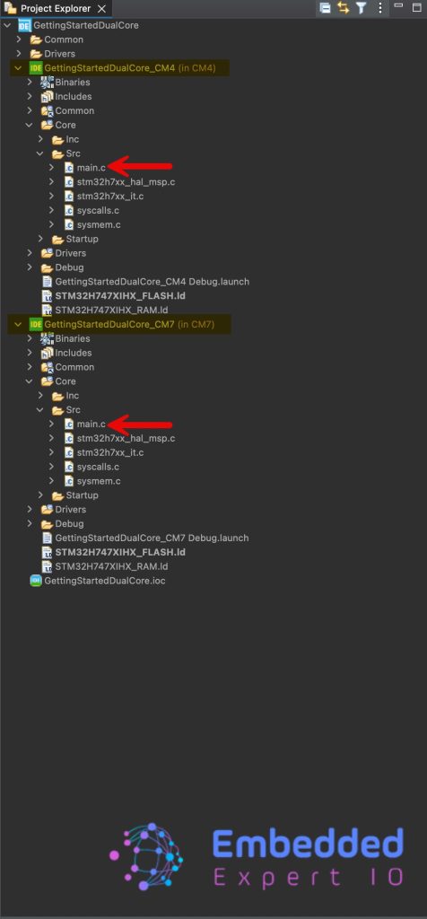
Since each project is separated, we can configure the debugger to flash CM4 through CM7.
Open main.c file for CM4 part of the project, in user code begin 3 in while loop, toggle the LED as follows:
HAL_GPIO_TogglePin(LEDM4_GPIO_Port, LEDM4_Pin);
HAL_Delay(500);
Next, open main.c for CM7 part, in user code begin 3, toggle the as follows:
HAL_GPIO_TogglePin(LEDM7_GPIO_Port, LEDM7_Pin);
HAL_Delay(200);
Now, click on build to build the project, you need to do for both, CM4 and CM7 since they are separated projects.
4. Project Configuration:
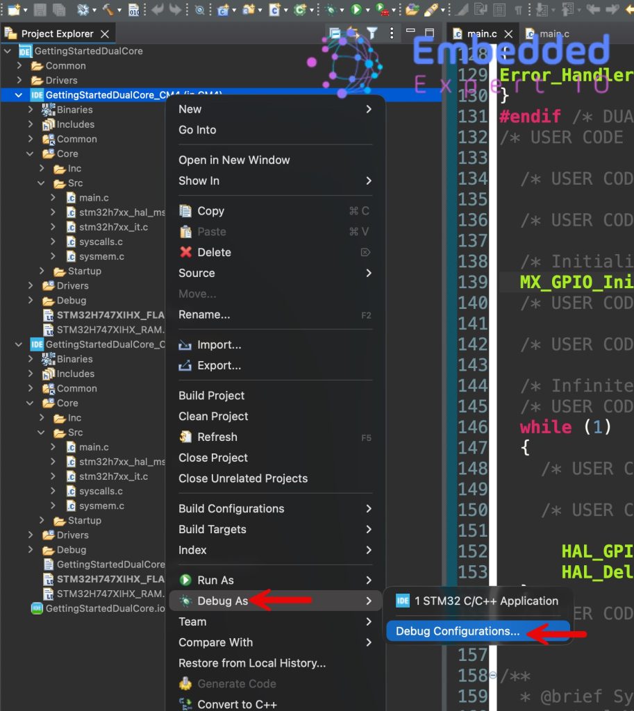
After the compilation, right click on CM7, select debug as and select Debug Configuration as follows:
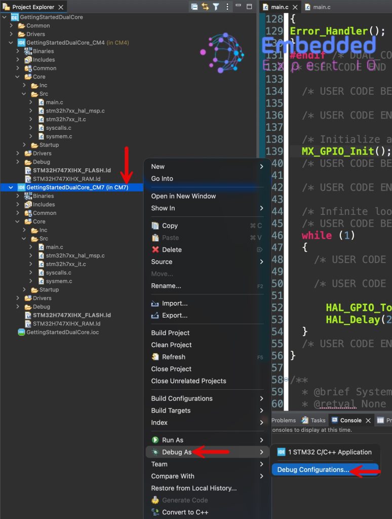
Create a new configuration by double click on STM32 C/C++ Application and configure it as follows:
From debugger:
- Take a note for the port number, needed later.
- Check halt all cores.
Note: in same window, in the bottom, you should make sure that Shared ST-Link is enabled (by default it is enabled).
Next, from startup tab, add new Load Image and Symbols:
- Project: The CM version.
- Build configuration: Debug.
- Click on Ok
Finally click on Apply then close.
Next, we shall configure the CM4 part of the project.
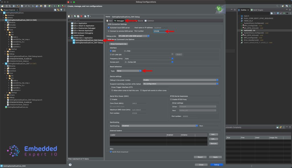
Right click on CM4 version of the project, debug as, debug configuration:
Create new debug configuration as select Debugger and configure it as follows:
- Set the port number at least 3 number higher than the one for CM7 (61238 in this case).
- Reset behaviour to None since it is being halted by CM7 core already.
Next, from startup, edit the current configuration and disable download as follows:
Finally, click Apply then Close.
Now, you can click on Run as follows:

5. Results:
As you can see, both LEDs are blinking which means we have successfully flashed both core at the same.
In part 2, we shall see how to start the debugging.
Stay tuned.
Happy coding 😉
Add Comment