This guide demonstrates how to interface a GLCD12864 display based on the ST7920 controller with an STM32 microcontroller using the U8G2 graphics library. We will cover hardware setup, library integration, and display initialization to build a solid foundation for graphical applications.
In this guide, we shall cover the following:
- Introduction.
- Connection.
- STM32CubeMX modification.
- Firmware modification.
- Results.
1. Introduction:
This guide focuses on interfacing a GLCD 128×64 display based on the ST7920 controller with an STM32 Nucleo development board using the U8G2 graphics library. The ST7920 is a versatile and widely used graphic LCD controller that supports both text and graphic modes, making it suitable for a variety of embedded applications such as control panels, data loggers, instrumentation displays, and custom user interfaces. On the other hand, the STM32 Nucleo series provides a powerful yet flexible platform for rapid prototyping with Arm Cortex-M microcontrollers, offering robust peripherals and wide community support.
The U8G2 graphics library adds another powerful layer by providing a high-level and hardware-independent API for rendering fonts, bitmaps, and geometric shapes on monochrome displays. With its optimized drawing routines and extensive font support, U8G2 allows developers to build attractive and functional interfaces without needing to manage low-level display driver code.
In this guide, we will cover the essential steps required to set up the hardware and software environment, configure the GLCD 128×64 with the STM32 Nucleo, and leverage U8G2 to render text and graphics. By the end, you will have a clear understanding of how to integrate this display into your own embedded projects and extend its functionality further.
2. Connection:
The connection as follows:
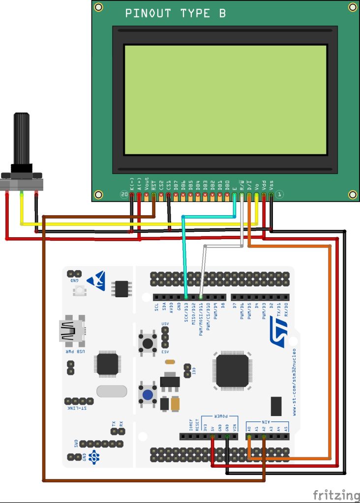
| ST7920 GLCD | STM32F411 Nucleo |
| Vss | GND |
| Vdd | 5V |
| Vo | Middle of Potentiometer |
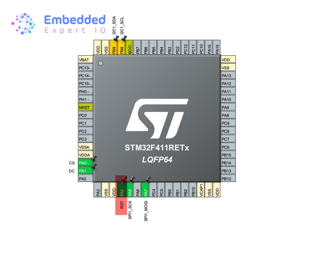
| DI (CS) | PA0 (A0 of Arduino connector) |
| R/W | MOSI (PA7) (Pin 11 of Arduino Connector) |
| E | SCK (PA5) (Pin 13 of Arduino Connector) |
| CS1 | GND |
| RST | PA4 (A2 of Arduino connector) |
| A (LED+) | 5V |
| K (LED-) | GND |
3. STM32CubeMX Modification:
From the previous project, open u8g2.ioc file as follows:
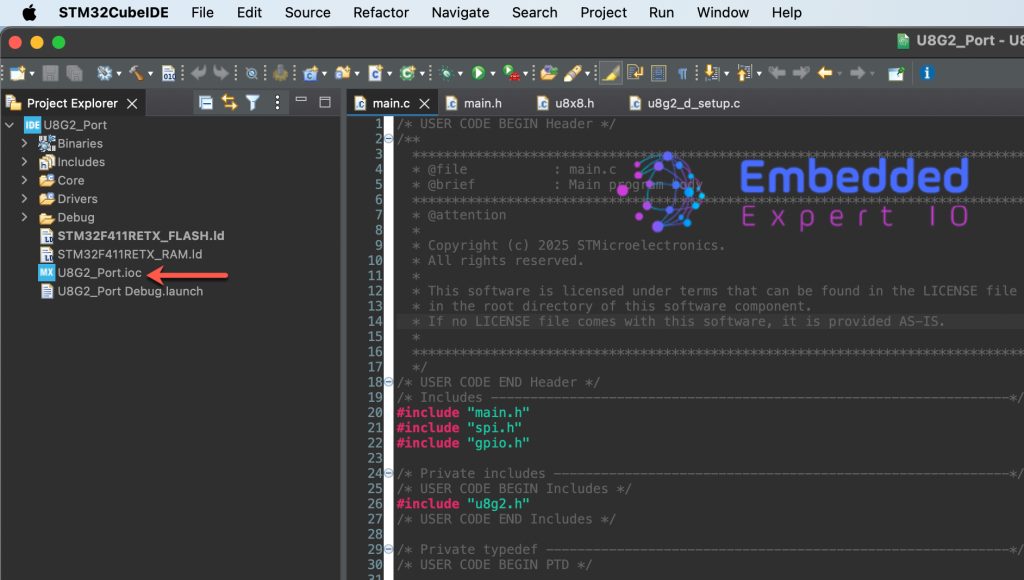
STM32CubeMX window shall appears.
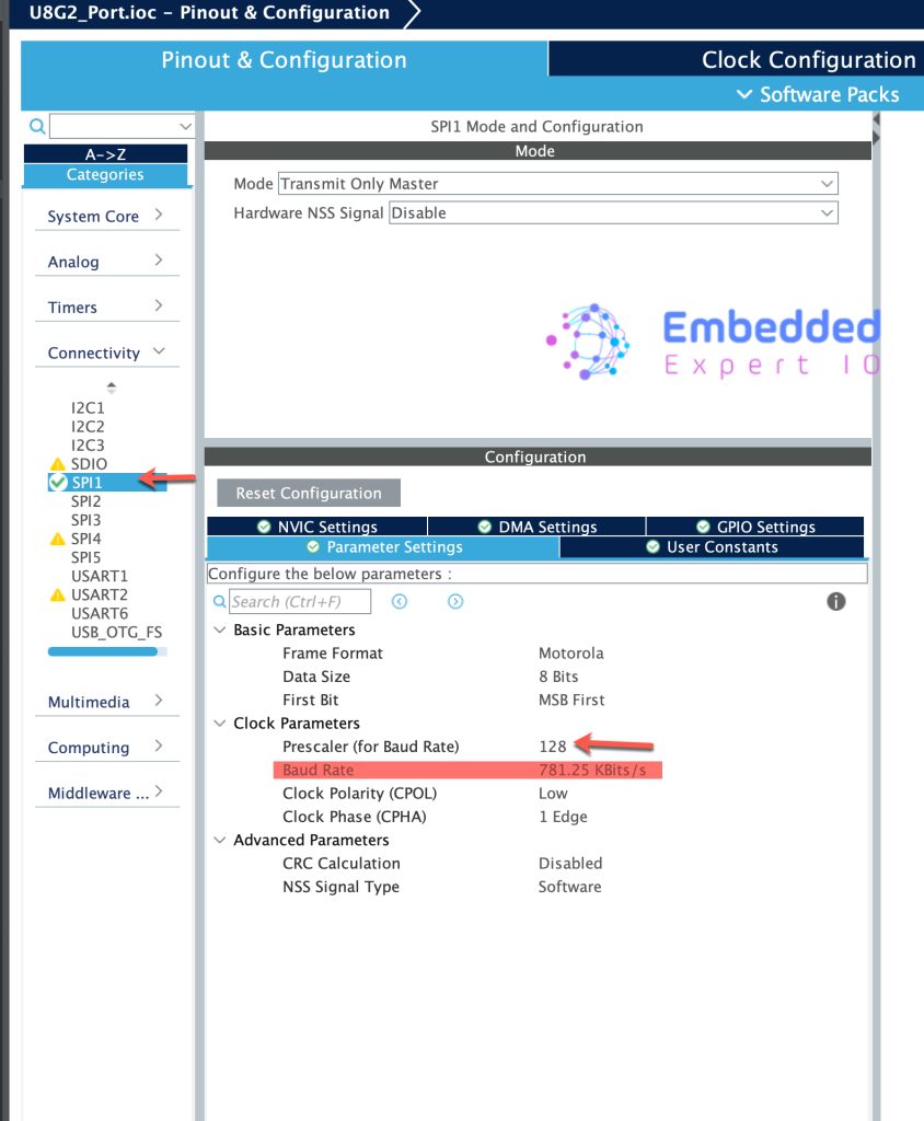
Next, head to SPI1 in connectivity and reduce to baud rate to be less than 1MBps as follows:
Next, set PA4 as GPIO Output and give a name of RST as follows:
Save the project and this will generate the code.
4. Firmware Modifications:
In uint8_t u8x8_gpio_and_delay function, add the following switch condition:
		case U8X8_MSG_GPIO_RESET:
			HAL_GPIO_WritePin(RST_GPIO_Port, RST_Pin, arg_int);
			break;
This will allow the library to reset the display using hardware reset.
For ST7920, the CS pin is different from any other chip select for any SPI peripheral. From the datasheet we can find the following:
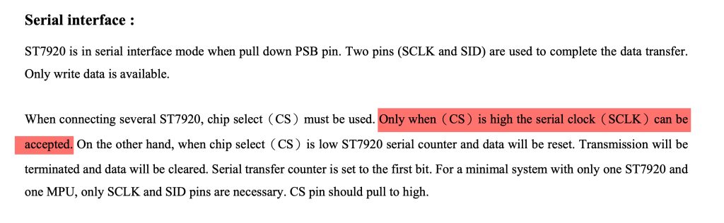
When CS pin is high, the ST7920 will accept the data and disabled when it is low.
Hence, in u8x8_spi function:
We need to switch the state of the CS pin as follows
		case U8X8_MSG_BYTE_START_TRANSFER:
			HAL_GPIO_WritePin(CS_GPIO_Port, CS_Pin, GPIO_PIN_SET);
			break;
		case U8X8_MSG_BYTE_END_TRANSFER:
			HAL_GPIO_WritePin(CS_GPIO_Port, CS_Pin, GPIO_PIN_RESET);
			break;
This will ensure the proper method to handle the communication.
In the user code begin 2 in the main function:
u8g2_Setup_st7920_s_128x64_f(&myDisplay, U8G2_R0, u8x8_spi, u8x8_gpio_and_delay);
Since the display uses st7920 we need to use st7920 setup function.
Next, draw a text and circle as follows:
  u8g2_ClearDisplay(&myDisplay);
  u8g2_SetFont(&myDisplay, u8g2_font_ncenB14_tr);
  u8g2_DrawStr(&myDisplay, 0,15,"Hello world");
  u8g2_DrawCircle(&myDisplay, 60, 30, 10, U8G2_DRAW_ALL);
  u8g2_SendBuffer(&myDisplay);
Thats all for the firmware. Save the project and run it on your MCU as follows:

5. Results:
You should get the following:

Happy coding 😉
Add Comment