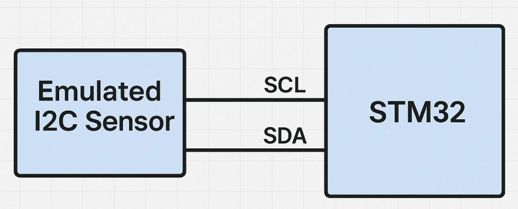
In this part of the guide, the emulated I²C sensor will act as a data source, sending predefined or dynamically generated values back to the master upon request. This simulates the behavior of real sensors, where the master first selects a register and then retrieves measurement or status data over the I²C bus.
In this guide, we shall cover the following:
- The need for Master to transmit data.
- Slave Firmware Development.
- Master Firmware Development.
- Results.
1. The Need for Master to Transmit Data:
In I²C communication, the master always controls the bus. The slave cannot decide on its own which data to send — it only responds when the master addresses it. For this reason, the master must typically perform a short write operation before a read, to tell the slave which register or memory location it wants to read from. This is true for almost all register-based sensors and EEPROM devices.
1. Register Selection Mechanism
Most sensors and memory devices internally store data in registers or memory cells, each identified by an address. The master doesn’t automatically know which register the slave will send data from. By transmitting the register address first, the master tells the slave “I want to read from here”. Without this step, the slave would have no context and might return invalid or stale data.
2. Maintaining Data Consistency
Sensors often contain multiple registers, such as configuration settings, measurement values, or status flags. If the master could only read blindly, it might receive unrelated or outdated information. The preceding write (register pointer)ensures that the returned data is consistent with the master’s request.
3. Support for Sequential Reads
Once the master transmits a starting register address, the slave can automatically increment its internal pointer. This allows the master to read multiple bytes in sequence (burst read) without having to send the address before every byte. For example, an accelerometer might send X, Y, and Z readings in one continuous transaction.
4. I²C Bus Protocol Rules
By design, I²C requires that the master initiates every communication, whether read or write. A slave cannot just broadcast its data. Even when the master wants to read, it must send the slave address and specify direction. When combined with a short write phase (register pointer), this guarantees deterministic and orderly communication between multiple devices on the bus.
2. Slave Firmware Development:
OPen main.c of slave project. In user code begin includes, include the following library:
#include "stdlib.h"
This will provide us access to random number generation.
In user code begin PV, declare the following array:
uint8_t SensorData[3]={0};This array will hold sensor data.
Declare the following:
#define ReadReg1 0x03
Here, ReadReg1 shall be transmitted by master to read the sensor data.
In HAL_I2C_AddrCallback in the else condition, means the master needs to read data:
if (RegisterData[0] == ReadReg1)
{
  SensorData[0] = rand() % 255;
  SensorData[1] = rand() % 255;
  SensorData[2] = rand() % 255;
  HAL_I2C_Slave_Seq_Transmit_IT(hi2c,SensorData, 3, I2C_FIRST_AND_LAST_FRAME);
}
else
{
  //TODO
}
If the first byte of the transmitted data match ReadReg1, send three random data.
Thats all for the slave configuration. Save the project and run it on your MCU as follows:

3. Master Firmware Development:
Open main.c of the Master project. In user code begin PV, declare the following array:
uint8_t SensorData[3];
This will hold the transmitted data from the slave which is 3 data for now.
In user code begin 3 in while 1 loop:
	  HAL_I2C_Mem_Read(&hi2c1, (0x1D<<1), 0x03, 1, SensorData, 3, 100);
	  HAL_Delay(100);
That all for the master configuration. Save the project and start a debugging session as follows:

4. Results:
By adding SensorData to Live expressions in the debugging session, you should get 3 random numbers as follows:
In next part, we shall use ADC with configuration data to set the sample rate and interrupt generation.
Stay tuned.
Happy coding 😉
Add Comment