PWM Input mode on STM32 timers is a powerful feature that allows the microcontroller to directly measure the characteristics of an incoming PWM signal, such as its frequency and duty cycle. By configuring the timer’s input capture channels appropriately, the signal’s high time and period can be automatically captured and processed with minimal CPU intervention.
In this guide, we shall cover the following:
- Introduction to PWM input mode.
- STM32CubeIDE setup.
- Firmware development.
- Connection.
- Results.
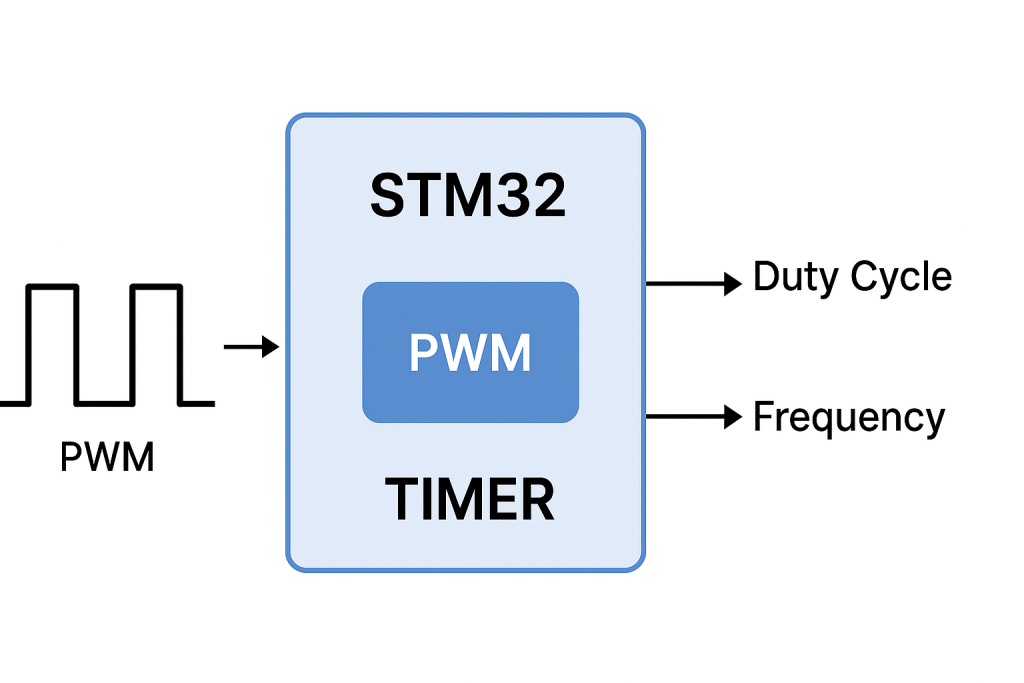
1. Introduction to PWM Input Mode:
PWM Input mode on STM32 timers is widely used when an external PWM signal needs to be measured and analyzed, such as in motor control, sensor interfaces, or communication with other devices that encode data into PWM pulses. In this mode, the timer is configured to operate with two input capture channels: one channel measures the period of the PWM signal, while the other captures the high time of the pulse. By comparing these two captured values, both the duty cycle and the frequency of the signal can be determined precisely.
Internally, the timer hardware takes care of synchronizing the capture events, eliminating the need for complex software routines to measure pulse widths. This makes the measurement accurate even at high input frequencies and ensures that CPU load remains low. For example, in motor speed monitoring, the incoming PWM from a speed sensor can be directly connected to the timer input, and the timer hardware will continuously capture the signal’s characteristics without requiring constant polling.
The main advantage of using PWM Input mode is that the process is entirely handled in hardware. This ensures robustness, reduces jitter, and improves measurement precision compared to software-based timing methods. Additionally, when combined with interrupts or DMA, the captured values can be transferred seamlessly into memory for further processing, allowing real-time systems to handle PWM measurements efficiently.
Because of these features, PWM Input mode is a cornerstone technique in many embedded applications, ranging from servo control feedback, ultrasonic sensor measurements, and digital communication decoding, to general-purpose frequency or duty cycle monitoring. It provides a reliable bridge between the analog world of pulse signals and the digital logic of the microcontroller, making it one of the most practical uses of STM32’s advanced timer peripherals.
2. STM32CubeIDE Setup:
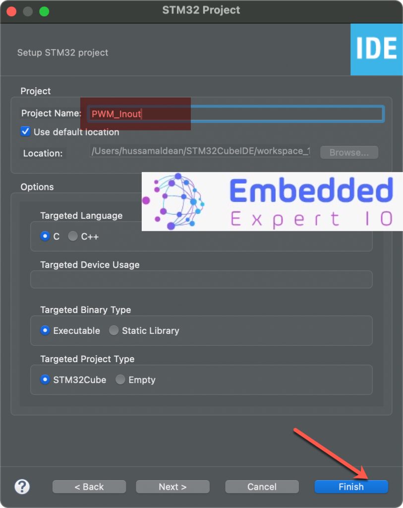
Open STM32CubeIDE after selecting the workspace and create new project as following:

Select the MCU:

Give the project a name:
Once the project has been created, STM32CubeMX window will appear.
From Clock configuration, set the system clock to maximum (100MHz in this case) and note the timer frequencies as follows:
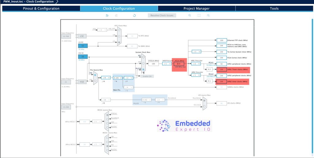
Notice that the timers have 100MHz clock frequency.
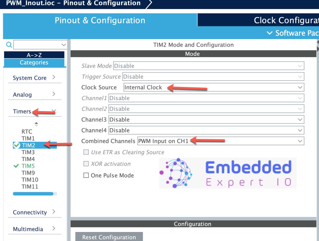
Next, we shall configure TIM2 to work in PWM input mode.
Head to timers section from Pinout and Configuration, select TIM2 and configure it as follows:
- Clock Source: Internal Clock
- Combined Channels: PWM Input in CH1
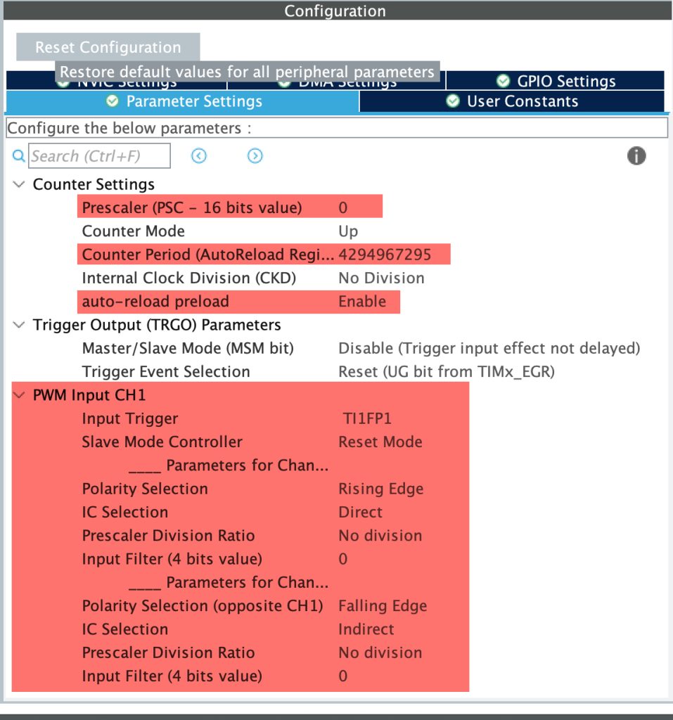
Next, in parameter Settings:
- Prescaler to 0 which means maximum speed.
- Counter period to maximum (32-bit 0xFFFFFFFF in this case).
- Enable auto-reload preload.
- Keep the rest as default.
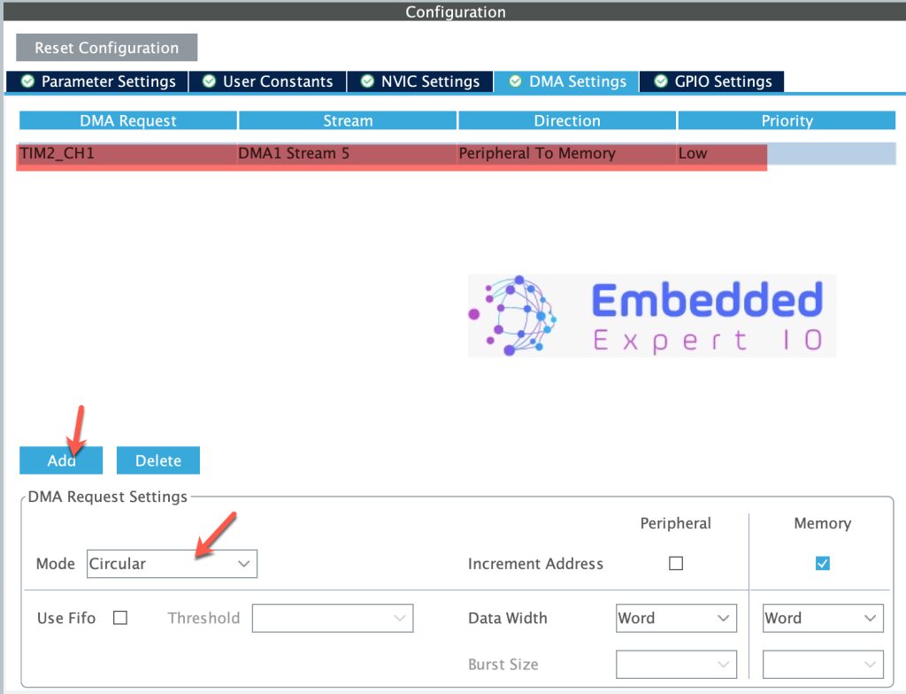
Next, enable DMA for TIM2_CH1 in circular mode as follows:
Next, we shall disable the interrupt for the DMA channel related to the timer as follows:
From system core, open NVIC, disable Enforce DMA interrupt and disable the DMA interrupt for the channel as follows:
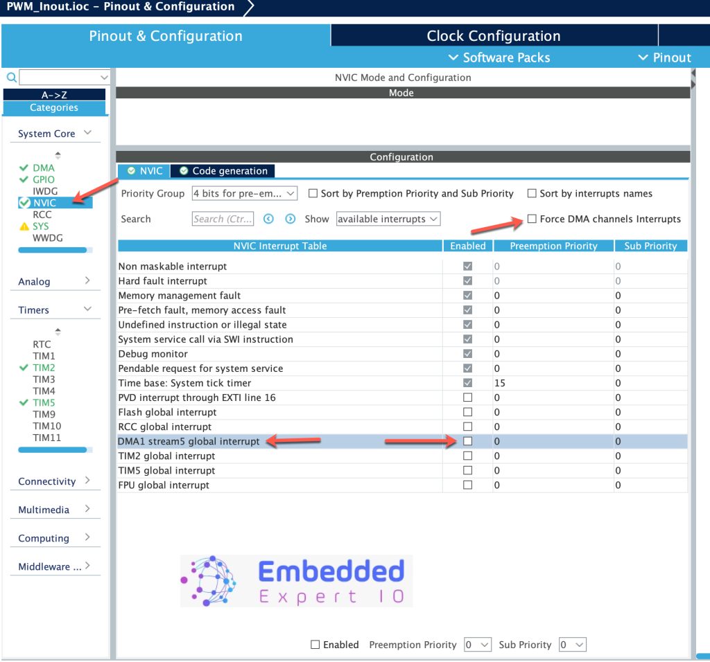
This way, we will ensure that no DMA interrupt generation will happen and impact the performance our MCU.
Next, we shall configure TIM5 to generate PWM signal as follows:
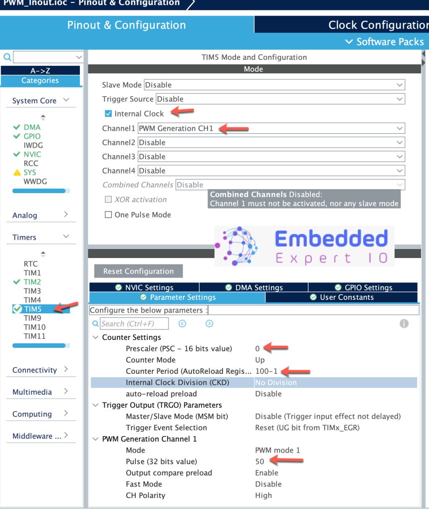
With these parameter, we shall generate PWM signal with 1 MHz frequency and 50% duty cycle. For more information about how to configure the timer in PWM mode, please refer to this guide.
That all for the configuration. Save the project and it should be generated.
3. Firmware Development:
Once the project is generated, main.c shall be opened.
Once the main.c has been opened, in user begin PV, declare the following variables:
uint32_t CCR1_Value;
This variable will hold the measured pulse length (Period) which will determine the frequency of the measured PWM.
uint32_t CCR2_Value;
This will hold the measured length of the pulse (Duty cycle of the PWM signal).
uint32_t frequency;

float duty;
These value shall hold the frequency and duty of the signal.
Next, in user begin 2 in main function, start TIM2_CH1 in input capture in DMA mode as follows:
HAL_TIM_IC_Start_DMA(&htim2, TIM_CHANNEL_1, &CCR1_Value, 1);
Start TIM2_CH2 in input capture normal mode as follows:
HAL_TIM_IC_Start(&htim2, TIM_CHANNEL_2);
Start the PWM signal:
HAL_TIM_PWM_Start(&htim5, TIM_CHANNEL_1);
Next, in user code begin 3 in while 1 loop:
First, calculate the frequency of the signal as follows:
frequency=100000000/(CCR1_Value);
Since the timer will trigger 100 million times per second and CCR1 hold how many pulses from these 100M lasted, by dividing 100M by the captured value, we can get the frequency. CCR1_Value is being updated by DMA, no need to read it manually.
Next, we shall read CCR2 to determine the duty cycle as follows:
CCR2_Value=HAL_TIM_ReadCapturedValue(&htim2, TIM_CHANNEL_2);
Calculate the duty cycle by dividing CCR2/CCR1 *100 as follows:
duty=(((float)CCR2_Value/(float)CCR1_Value))*100.0;
Repeat the cycle each 10 milliseconds:
HAL_Delay(10);
Thats all for the firmware.
Build the project and start a debugging session as following:

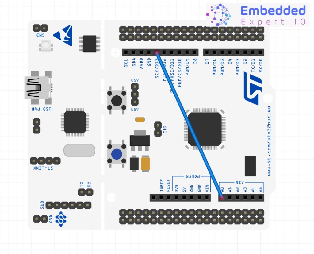
4. Connection:
Since TIM2_CH1 and TIM5_CH1 are PA0 and PA5 respectively. Hence, the connection as follows:
5. Results:
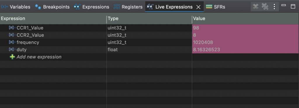
Add CCR1_Value, CCR2_Value, duty and frequency to Live Expression
1MHz test:
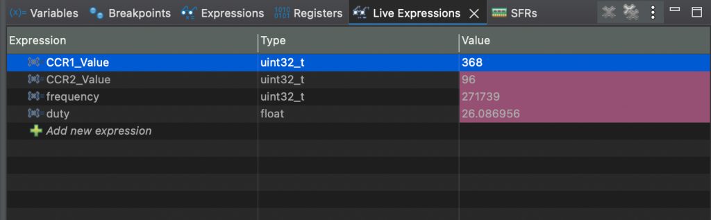
10MHz test:
1KHz:
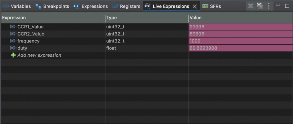
It is usable to 5MHz, beyond this, it will drift in terms of measurement.
Happy coding 😉
Add Comment