Differential mode in the STM32 ADC allows measurements based on the voltage difference between two input pins rather than a single-ended signal referenced to ground. This approach greatly improves noise immunity, increases measurement accuracy for small signals, and is ideal for applications involving sensors or signals with common-mode interference.
In this guide, we shall cover the following:
- What is differential mode.
- STM32CubeMX Setup.
- Importing project to STM32CubeIDE.
- Firmware development.
- Results.
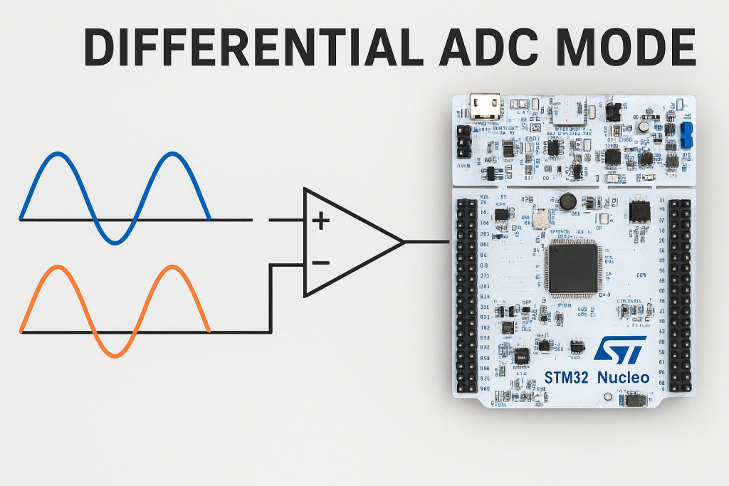
1. What is Differential Mode:
Differential mode in the STM32 ADC allows the converter to measure the voltage difference between two input pins instead of referencing all measurements to ground. This technique significantly enhances noise immunity, improves accuracy for low-level signals, and enables the ADC to reject common-mode interference that appears equally on both inputs.
Differential ADCs are generally used in applications requiring high precision, noise reduction, and increased dynamic range. In this tutorial we will specifically focus on just measuring the voltage difference between the two differential inputs. The ADC data will be based on this differential voltage, which we will later convert into the voltage.
Not all the STM32 devices support differential ADC. I am going to use the STM32L476RG Nucleo board. However, some explanation will be related to 16-bit ADC.
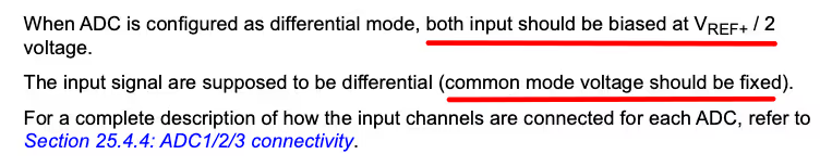
As mentioned in the reference manual both the differential inputs should be biased at Vref/2. The Vref is a custom reference voltage which can be provided externally, but the hardware on the board should be configured accordingly. By default the Vref is connected to the VDDA (& VCC), therefore the Vref is 3.3V.
Biasing means that instead of fluctuating around 0V, the signals should be centred around 1.65V.
We should also take care of the Common mode voltage (CMV). This Common-mode voltage is the average voltage of two input signals in a differential system. This voltage only has a small range in STM32. You can see it in the image from datasheet of the device.
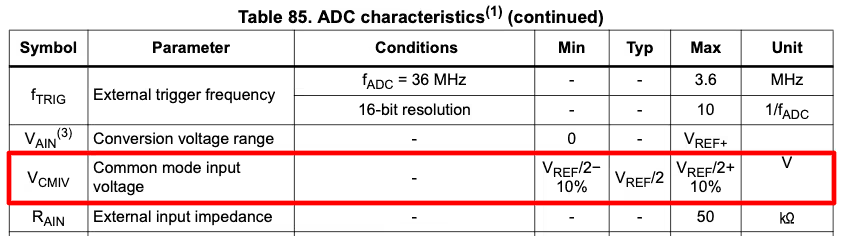
You can see the common mode voltage varies by only 10% from Vref/2 voltage. So if the Vref is at 3.3V, the common mode voltage can vary from around 1.48 V to 1.82V.
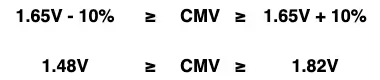
When choosing the input voltages on both the differential pairs make sure the average of both voltages lies within this range. It does not mean that it will not work outside this range rather the result outside this range is unpredictable. In certain cases it might work while in other cases it won’t.
The ADC will convert the voltage difference between both the input pins as per the formula shown below.
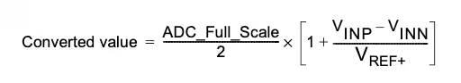
- If the VINN = 0 and VINP = VREF, the ADC value will be equal to the MAXIMUM.
- Whereas when VINN = VREF and VINP = 0, the ADC value will be equal to the 0.
- When VINN = VINP, the ADC value will be exactly HALF the MAXIMUM.
Below is the image showing the range of ADC value based on the differential inputs. The VDIFF is the voltage difference between the input signals.
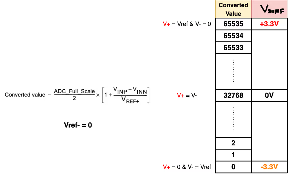
We will write our code in such a way that the ADC MAXIMUM (65535) indicates a +3.3V while the ADC MINIMUM (0) indicates a -3.3V. Also the ADC MAX/2 (32768) will indicate 0V.
Reference: Controllerstech.
2. STM32CubeMX Setup:
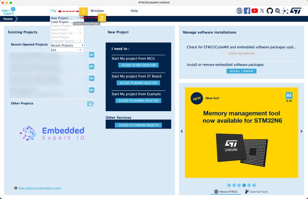
Open STM32CubeMX as start a new project as follows:
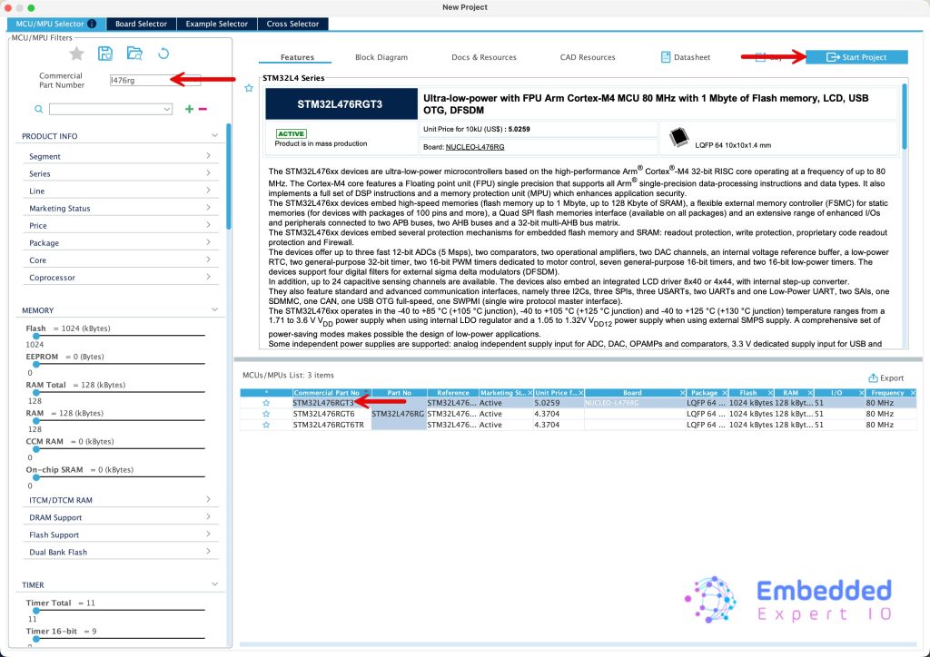
Search for your STM32 MCU, select the MCU and click on Start New Project as follows:
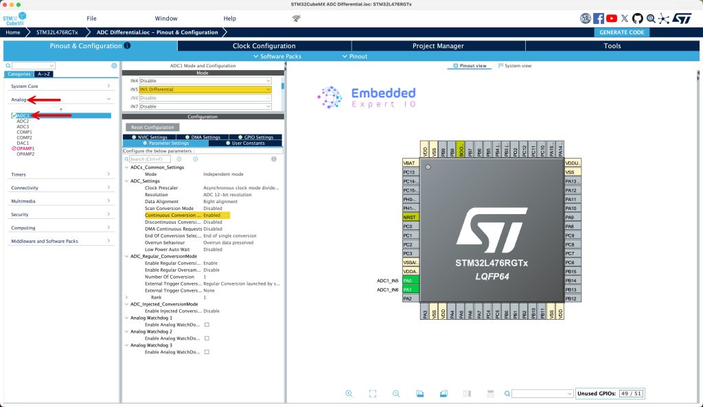
Next, from Analog, select ADC1 and set IN5 as differential and configure the ADC as follows:
- Enable Continuous Conversion.
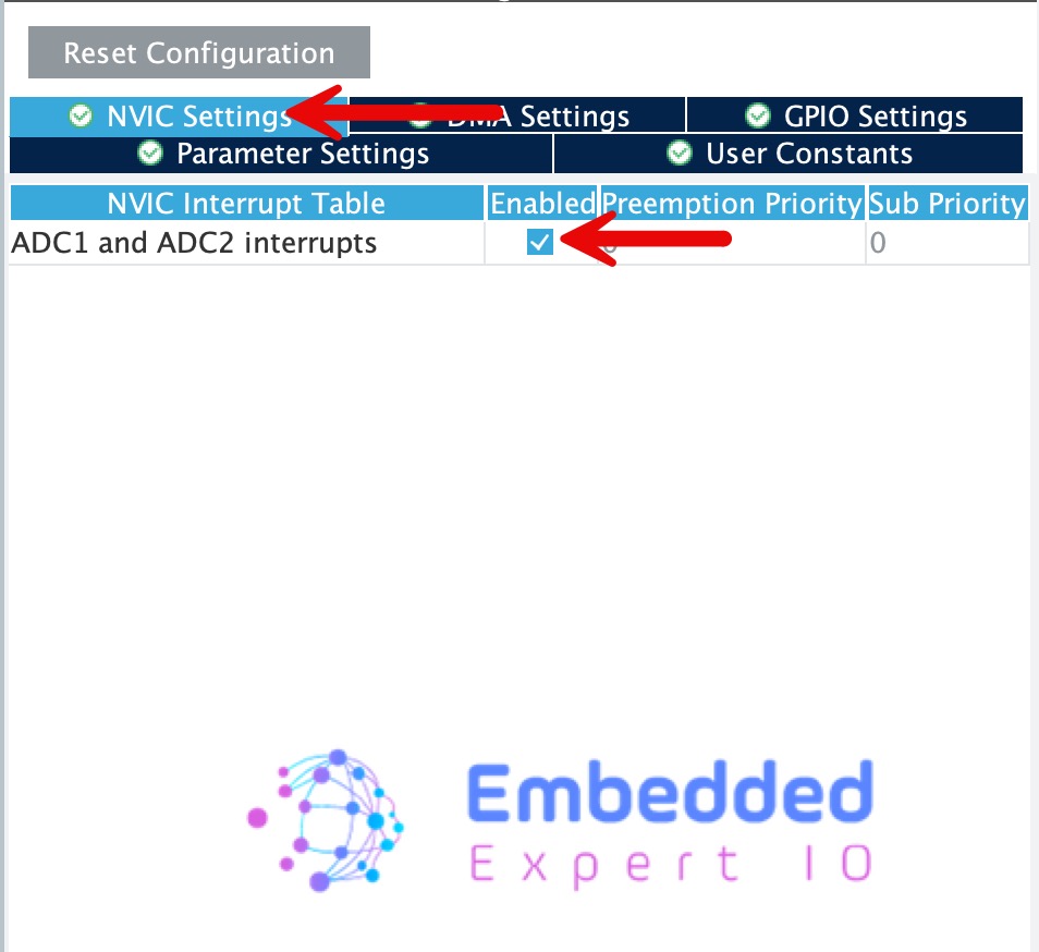
Next, from NVIC tab, enable ADC interrupt as follows:
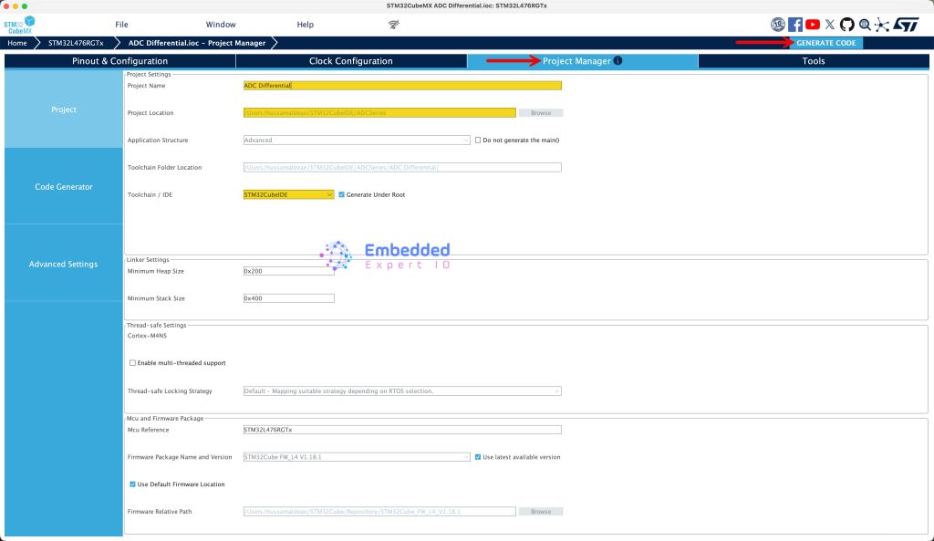
Next, from Project manager
- Give the project a name.
- Set the project location.
- Toolchain/IDE STM32CubeIDE.
- Click on generate project.
Thats all for STM32CubeMX configuration.
3. Importing project to STM32CubeIDE:
Open STM32CubeIDE, select your workspace and click on Launch.
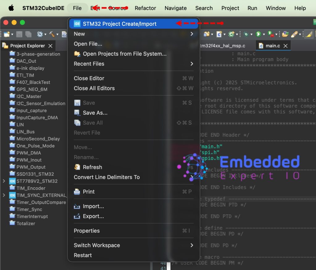
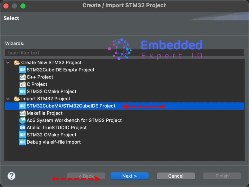
From the IDE, click File and select STM32 Project Create/Import as follows:
Next, from Import STM32 Project, select STM32CubeMX/STM32CubeIDE Project and click on Next as follows:
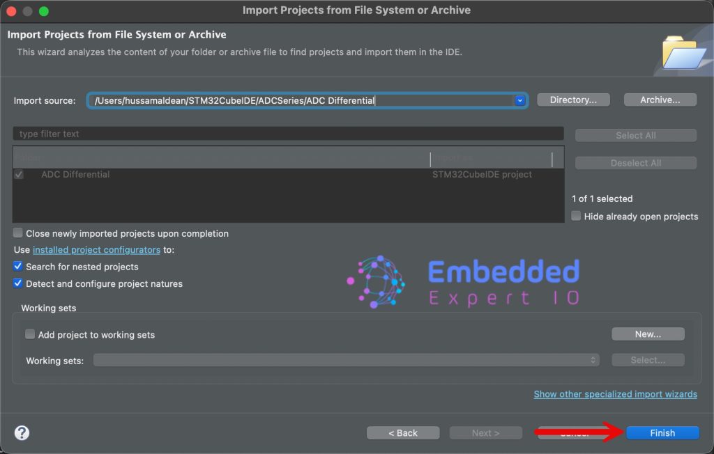
Next, select the folder that contains the .ioc file and click on Finish as follows:
4. Firmware Development:
Open main.c file
In main.c file, in user code begin PV, declare the following variables:
uint16_t ADC_VAL;
int voltage;
ADC_VAL is the raw adc value measure by ADC in differential mode for IN5.
Voltage, is the difference voltage between INP and INN.
For ADC conversion completed function:
void HAL_ADC_ConvCpltCallback(ADC_HandleTypeDef *hadc)
{

	ADC_VAL = HAL_ADC_GetValue(&hadc1);
	voltage = (3300*2*ADC_VAL/4095)-3300;

}
In user code begin 2 in main function, start the ADC in interrupt mode as follows:
HAL_ADC_Start_IT(&hadc1);
Thats all for the project.
5. Results:
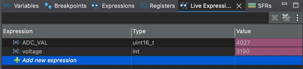
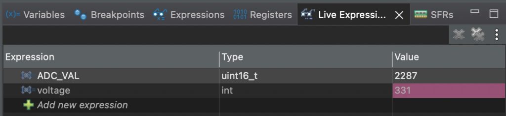
Start a debugging session and add ADC_VAL and voltage to live expression.
When 3.3V is applied to IN5_P and 0 to IN5_N:
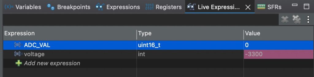
When 3.3V is applied to IN5_N and 0 to IN5_P:
When 2.5V is applied to IN5_P and 2V to IN5_N:
When 2.5V is applied to IN5_N and 2V to IN5_P:
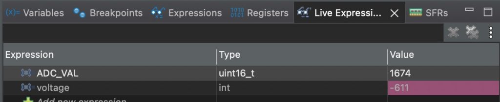
Note that we are able to measure the difference between two points without any issue.
Also, my function generator can provide up to 2.45 rather than 2.5V which explains less voltage than 500mV difference in both case.
Happy coding 😉
Add Comment