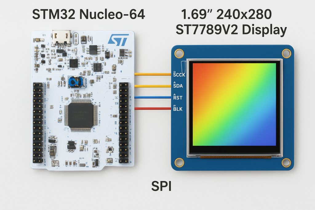
In this second part of the guide, we move from configuration to implementation by developing the ST7789V2 driver header and source files for STM32. We will initialize the LCD controller and implement a basic draw-pixel function, using it to render randomly colored pixels as a first functional test of the display.
In this guide, we shall cover the following:
- Creating source and header file.
- Developing the header file.
- Developing the source file.
- Main.c code.
- Results.
5. Creating Source and Header File:
First, we need to create new source and header files.
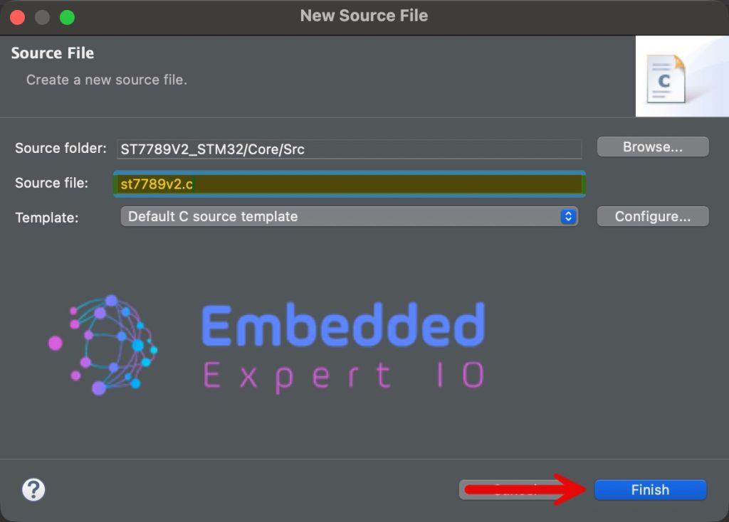
To create Source file, right click on Src folder and add new source file as following:
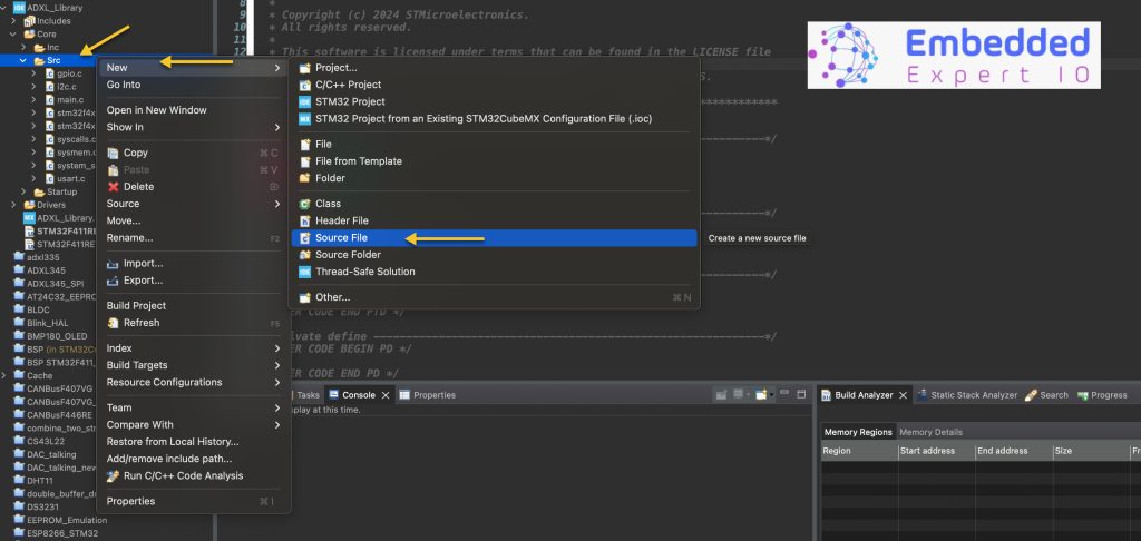
Give a name for the source file, we shall name it as st7789v2.c as following:
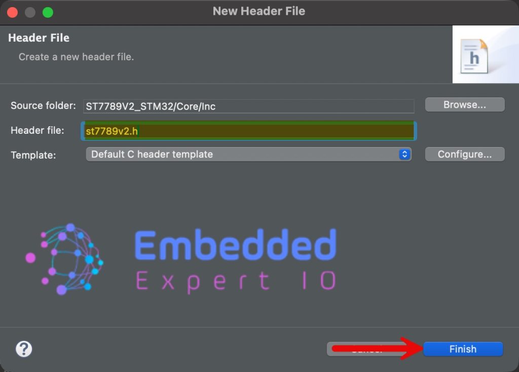
n similar manner, right click on Inc folder and add new header file with name of st7789v2.h.
6. Developing the Header File:
Within st7789v2.h file, we start by including the following header files:
#include <stdint.h>

#include "main.h"

#include "spi.h"
- stdint allows us to access uint8_t etc variable type.
- main.h for main STM32 header file to access HAL basic functions like HAL_Delay etc.
- spi.h allows to access to SPI peripheral related function.
Next, define the size of the display:
#define ST7789V2_HEIGHT 280
#define ST7789V2_WIDTH 240
Orientation of the display:
#define HORIZONTAL 0
#define VERTICAL   1
Functions related to display initialization and draw pixel:
void LCD_Init(uint8_t Scan_dir);

void Draw_Pixel(uint16_t X, uint16_t Y, uint16_t Color);
Hence, the entire header file as follows:
#ifndef INC_ST7789V2_H_
#define INC_ST7789V2_H_


#include <stdint.h>

#include "main.h"

#include "spi.h"

#define ST7789V2_HEIGHT 280
#define ST7789V2_WIDTH 240


#define HORIZONTAL 0
#define VERTICAL   1

void LCD_Init(uint8_t Scan_dir);

void Draw_Pixel(uint16_t X, uint16_t Y, uint16_t Color);


#endif /* INC_ST7789V2_H_ */
7. Developing the Source File:
We start by including st7789v2 header file as follows:
#include <st7789v2.h>
Data structure to hold some required data:
typedef struct{
    uint16_t WIDTH;
    uint16_t HEIGHT;
    int8_t SCAN_DIR;
}LCD_ATTRIBUTES;
Declare the data structure as follows:
LCD_ATTRIBUTES lcdAttr;
Next, we need some functions to handle the CS, CD and RST pins:
static void CS_Deselect()
{
	HAL_GPIO_WritePin(CS_GPIO_Port, CS_Pin, SET);
}

static void CS_Select()
{
	HAL_GPIO_WritePin(CS_GPIO_Port, CS_Pin, RESET);
}

static void RST_HIGH()
{
	HAL_GPIO_WritePin(RST_GPIO_Port, RST_Pin, SET);
}

static void RST_LOW()
{
	HAL_GPIO_WritePin(RST_GPIO_Port, RST_Pin, RESET);
}

static void DC_HIGH()
{
	HAL_GPIO_WritePin(DC_GPIO_Port, DC_Pin, SET);
}

static void DC_LOW()
{
	HAL_GPIO_WritePin(DC_GPIO_Port, DC_Pin, RESET);
}
These are standardized for any color LCD.
Next, function that will hardware reset the display:
static void Reset(void)
{
	RST_HIGH();
    HAL_Delay(100);
    RST_LOW();
    HAL_Delay(100);
    RST_HIGH();
    HAL_Delay(100);
}
The reset sequence as follows:
- Set RST pin to high and wait for 100ms.
- Set it low and wait for 100ms.
- Set it high again and wait for 100ms.
Next, function that will write data, command and 16-bit data as follows:
static void WriteData(uint8_t data)
{
	CS_Select();
	DC_HIGH();

	HAL_SPI_Transmit(&hspi1, &data, 1, 10);

	CS_Deselect();

}

static void WriteCommand(uint8_t Command)
{
	CS_Select();
	DC_LOW();

	HAL_SPI_Transmit(&hspi1, &Command, 1, 10);

	CS_Deselect();

}

static void WriteData16Bit(uint16_t data)
{
	CS_Select();
	DC_HIGH();

	uint8_t data16_bit[2]={(data>>8)&0xFF, data&0xFF};

	HAL_SPI_Transmit(&hspi1, data16_bit, 2, 10);

	CS_Deselect();

}
These are also standard for any color LCD.
Next, software reset of the display:
static void soft_Reset(void)
{
	WriteCommand(0x01);
	HAL_Delay(15);
}
Next, register initialization of the display:
static void LCD_InitReg(void)
{
    WriteCommand(0x36);
    WriteData(0x00);

    WriteCommand(0x3A);
    WriteData(0x05);

    WriteCommand(0xB2);
    WriteData(0x0B);
    WriteData(0x0B);
    WriteData(0x00);
    WriteData(0x33);
    WriteData(0x35);

    WriteCommand(0xB7);
    WriteData(0x11);

    WriteCommand(0xBB);
    WriteData(0x35);

    WriteCommand(0xC0);
    WriteData(0x2C);

    WriteCommand(0xC2);
    WriteData(0x01);

    WriteCommand(0xC3);
    WriteData(0x0D);

    WriteCommand(0xC4);
    WriteData(0x20);

    WriteCommand(0xC6);
    WriteData(0x13);

    WriteCommand(0xD0);
    WriteData(0xA4);
    WriteData(0xA1);

    WriteCommand(0xD6);
    WriteData(0xA1);

    WriteCommand(0xE0);
    WriteData(0xF0);
    WriteData(0x06);
    WriteData(0x0B);
    WriteData(0x0A);
    WriteData(0x09);
    WriteData(0x26);
    WriteData(0x29);
    WriteData(0x33);
    WriteData(0x41);
    WriteData(0x18);
    WriteData(0x16);
    WriteData(0x15);
    WriteData(0x29);
    WriteData(0x2D);

    WriteCommand(0xE1);
    WriteData(0xF0);
    WriteData(0x04);
    WriteData(0x08);
    WriteData(0x08);
    WriteData(0x07);
    WriteData(0x03);
    WriteData(0x28);
    WriteData(0x32);
    WriteData(0x40);
    WriteData(0x3B);
    WriteData(0x19);
    WriteData(0x18);
    WriteData(0x2A);
    WriteData(0x2E);

    WriteCommand(0xE4);
    WriteData(0x25);
    WriteData(0x00);
    WriteData(0x00);

    WriteCommand(0x21);

    WriteCommand(0x11);
    HAL_Delay(120);
    WriteCommand(0x29);
}
This initialization routine configures the ST7789V2 display controller by programming its core operating parameters, including memory access behavior, pixel format, power settings, frame rate, and gamma correction. The sequence starts by setting the memory data access control (0x36) and pixel format (0x3A) to define orientation and RGB565 color mode, followed by porch control, gate control, and voltage-related commands (0xB2–0xD6) that stabilize the panel’s timing and power characteristics.
The gamma correction commands (0xE0 and 0xE1) configure the positive and negative voltage curves, which directly affect color accuracy and contrast on the LCD. Additional commands such as display inversion (0x21) and extended control (0xE4) fine-tune visual behavior. Finally, the display is brought out of sleep mode using Sleep Out (0x11), followed by a mandatory delay to allow internal circuits to stabilize, and then Display ON (0x29) is issued to activate the panel and begin normal operation.
This sequence ensures the display is electrically stable, correctly timed, and visually calibrated before any pixel data is transmitted.
Next, setting display attributes as follows:
static void LCD_SetAttributes(uint8_t Scan_dir)
{
    // Get the screen scan direction
	lcdAttr.SCAN_DIR = Scan_dir;
    uint8_t MemoryAccessReg = 0x00;

    // Get GRAM and LCD width and height
    if (Scan_dir == HORIZONTAL) {
    	lcdAttr.HEIGHT = ST7789V2_WIDTH;
    	lcdAttr.WIDTH = ST7789V2_HEIGHT;
        MemoryAccessReg = 0X70;
    }
    else {
    	lcdAttr.HEIGHT = ST7789V2_HEIGHT;
    	lcdAttr.WIDTH = ST7789V2_WIDTH;
        MemoryAccessReg = 0X00;
    }

    // Set the read / write scan direction of the frame memory
    WriteCommand(0x36); // MX, MY, RGB mode
    WriteData(MemoryAccessReg); // 0x08 set RGB
}
This will allow the firmware to adjust the behaviour according to the orientation.
Next, LCD initialization function:
void LCD_Init(uint8_t Scan_dir)
{

    // Hardware reset
	Reset();

	//software reset
	soft_Reset();

    // Set the resolution and scanning method of the screen
	LCD_SetAttributes(Scan_dir);

    // Set the initialization register
	LCD_InitReg();
}
Next, set address window function:
static void LCD_SetWindows(uint16_t Xstart, uint16_t Ystart, uint16_t Xend, uint16_t Yend)
{
    if (lcdAttr.SCAN_DIR == VERTICAL) {
				// set the X coordinates
    	WriteCommand(0x2A);
    	WriteData(Xstart >> 8);
    	WriteData(Xstart);
    	WriteData((Xend-1) >> 8);
    	WriteData(Xend-1);

        // set the Y coordinates
        WriteCommand(0x2B);
        WriteData((Ystart+10) >> 8);
        WriteData(Ystart+10);
        WriteData((Yend+10-1) >> 8);
        WriteData(Yend+10-1);

    }
    else {
        // set the X coordinates
    	WriteCommand(0x2A);
    	WriteData((Xstart+10) >> 8);
    	WriteData(Xstart+10);
    	WriteData((Xend+10-1) >> 8);
    	WriteData(Xend+10-1);

        // set the Y coordinates
        WriteCommand(0x2B);
        WriteData(Ystart >> 8);
        WriteData(Ystart);
        WriteData((Yend-1) >> 8);
        WriteData(Yend-1);
    }

    WriteCommand(0X2C);
}
This function defines the active drawing window (addressing region) inside the ST7789V2’s internal GRAM before any pixel data is written. It uses the Column Address Set (0x2A) and Row Address Set (0x2B) commands to specify the start and end coordinates of the region where subsequent pixel data will be applied.
The behavior changes based on the selected scan direction: when vertical scanning is enabled, the X and Y axes are mapped differently to match the display orientation. The added offset (+10) compensates for the panel’s internal pixel mapping, which is common on ST7789-based displays where the visible area does not start at GRAM coordinate (0,0). Finally, the Memory Write command (0x2C) is issued, indicating that the next transmitted data bytes represent pixel color values for the defined window.
Finally draw pixel function:
void Draw_Pixel(uint16_t X, uint16_t Y, uint16_t Color)
{
	LCD_SetWindows(X, Y, X, Y);
	WriteData16Bit(Color);
}
Hence, the source file as follows:
#include <st7789v2.h>


typedef struct{
    uint16_t WIDTH;
    uint16_t HEIGHT;
    int8_t SCAN_DIR;
}LCD_ATTRIBUTES;

LCD_ATTRIBUTES lcdAttr;


static void CS_Deselect()
{
	HAL_GPIO_WritePin(CS_GPIO_Port, CS_Pin, SET);
}

static void CS_Select()
{
	HAL_GPIO_WritePin(CS_GPIO_Port, CS_Pin, RESET);
}

static void RST_HIGH()
{
	HAL_GPIO_WritePin(RST_GPIO_Port, RST_Pin, SET);
}

static void RST_LOW()
{
	HAL_GPIO_WritePin(RST_GPIO_Port, RST_Pin, RESET);
}

static void DC_HIGH()
{
	HAL_GPIO_WritePin(DC_GPIO_Port, DC_Pin, SET);
}

static void DC_LOW()
{
	HAL_GPIO_WritePin(DC_GPIO_Port, DC_Pin, RESET);
}


static void Reset(void)
{
	RST_HIGH();
    HAL_Delay(100);
    RST_LOW();
    HAL_Delay(100);
    RST_HIGH();
    HAL_Delay(100);
}


static void WriteData(uint8_t data)
{
	CS_Select();
	DC_HIGH();

	HAL_SPI_Transmit(&hspi1, &data, 1, 10);

	CS_Deselect();

}

static void WriteCommand(uint8_t Command)
{
	CS_Select();
	DC_LOW();

	HAL_SPI_Transmit(&hspi1, &Command, 1, 10);

	CS_Deselect();

}

static void WriteData16Bit(uint16_t data)
{
	CS_Select();
	DC_HIGH();

	uint8_t data16_bit[2]={(data>>8)&0xFF, data&0xFF};

	HAL_SPI_Transmit(&hspi1, data16_bit, 2, 10);

	CS_Deselect();

}


static void soft_Reset(void)
{
	WriteCommand(0x01);
	HAL_Delay(15);
}


static void LCD_InitReg(void)
{
    WriteCommand(0x36);
    WriteData(0x00);

    WriteCommand(0x3A);
    WriteData(0x05);

    WriteCommand(0xB2);
    WriteData(0x0B);
    WriteData(0x0B);
    WriteData(0x00);
    WriteData(0x33);
    WriteData(0x35);

    WriteCommand(0xB7);
    WriteData(0x11);

    WriteCommand(0xBB);
    WriteData(0x35);

    WriteCommand(0xC0);
    WriteData(0x2C);

    WriteCommand(0xC2);
    WriteData(0x01);

    WriteCommand(0xC3);
    WriteData(0x0D);

    WriteCommand(0xC4);
    WriteData(0x20);

    WriteCommand(0xC6);
    WriteData(0x13);

    WriteCommand(0xD0);
    WriteData(0xA4);
    WriteData(0xA1);

    WriteCommand(0xD6);
    WriteData(0xA1);

    WriteCommand(0xE0);
    WriteData(0xF0);
    WriteData(0x06);
    WriteData(0x0B);
    WriteData(0x0A);
    WriteData(0x09);
    WriteData(0x26);
    WriteData(0x29);
    WriteData(0x33);
    WriteData(0x41);
    WriteData(0x18);
    WriteData(0x16);
    WriteData(0x15);
    WriteData(0x29);
    WriteData(0x2D);

    WriteCommand(0xE1);
    WriteData(0xF0);
    WriteData(0x04);
    WriteData(0x08);
    WriteData(0x08);
    WriteData(0x07);
    WriteData(0x03);
    WriteData(0x28);
    WriteData(0x32);
    WriteData(0x40);
    WriteData(0x3B);
    WriteData(0x19);
    WriteData(0x18);
    WriteData(0x2A);
    WriteData(0x2E);

    WriteCommand(0xE4);
    WriteData(0x25);
    WriteData(0x00);
    WriteData(0x00);

    WriteCommand(0x21);

    WriteCommand(0x11);
    HAL_Delay(120);
    WriteCommand(0x29);
}

static void LCD_SetAttributes(uint8_t Scan_dir)
{
    // Get the screen scan direction
	lcdAttr.SCAN_DIR = Scan_dir;
    uint8_t MemoryAccessReg = 0x00;

    // Get GRAM and LCD width and height
    if (Scan_dir == HORIZONTAL) {
    	lcdAttr.HEIGHT = ST7789V2_WIDTH;
    	lcdAttr.WIDTH = ST7789V2_HEIGHT;
        MemoryAccessReg = 0X70;
    }
    else {
    	lcdAttr.HEIGHT = ST7789V2_HEIGHT;
    	lcdAttr.WIDTH = ST7789V2_WIDTH;
        MemoryAccessReg = 0X00;
    }

    // Set the read / write scan direction of the frame memory
    WriteCommand(0x36); // MX, MY, RGB mode
    WriteData(MemoryAccessReg); // 0x08 set RGB
}

void LCD_Init(uint8_t Scan_dir)
{

    // Hardware reset
	Reset();

	//software reset
	soft_Reset();

    // Set the resolution and scanning method of the screen
	LCD_SetAttributes(Scan_dir);

    // Set the initialization register
	LCD_InitReg();
}

static void LCD_SetWindows(uint16_t Xstart, uint16_t Ystart, uint16_t Xend, uint16_t Yend)
{
    if (lcdAttr.SCAN_DIR == VERTICAL) {
				// set the X coordinates
    	WriteCommand(0x2A);
    	WriteData(Xstart >> 8);
    	WriteData(Xstart);
    	WriteData((Xend-1) >> 8);
    	WriteData(Xend-1);

        // set the Y coordinates
        WriteCommand(0x2B);
        WriteData((Ystart+10) >> 8);
        WriteData(Ystart+10);
        WriteData((Yend+10-1) >> 8);
        WriteData(Yend+10-1);

    }
    else {
        // set the X coordinates
    	WriteCommand(0x2A);
    	WriteData((Xstart+10) >> 8);
    	WriteData(Xstart+10);
    	WriteData((Xend+10-1) >> 8);
    	WriteData(Xend+10-1);

        // set the Y coordinates
        WriteCommand(0x2B);
        WriteData(Ystart >> 8);
        WriteData(Ystart);
        WriteData((Yend-1) >> 8);
        WriteData(Yend-1);
    }

    WriteCommand(0X2C);
}

void Draw_Pixel(uint16_t X, uint16_t Y, uint16_t Color)
{
	LCD_SetWindows(X, Y, X, Y);
	WriteData16Bit(Color);
}
8. Main.c code:
In user code includes in main.c file, include the following:
#include "st7789v2.h"

#include "stdlib.h" //for random
In user code begin 2 in main function, initialize the LCD in vertical orientation:
LCD_Init(VERTICAL);
In user code begin 3 in while loop:
File each pixel with random color as follows:
for (int i=0;i<ST7789V2_WIDTH ;i++)
	  {
		  for (int j=0;j<ST7789V2_HEIGHT;j++)
		  {
			  Draw_Pixel(i,j,random()%0xFFFF);
		  }
	  }
Thats all.
Save the project, build it and run it on your board as following:

9. Results:
Once the IDE finish flashing, you should get random colors on you display, for example:

In part 3, we shall display an image.
Stay tuned.
Happy coding 😉
Add Comment