Emulating an I2C sensor using an STM32 microcontroller allows developers to simulate the behavior of real sensors for testing or development purposes. By configuring the STM32 as an I2C slave device, it can respond to read and write operations just like a physical sensor would on the bus.
This guide shall cover the following:
- Introduction.
- I2C Slave Configuration.
- I2C Master Configuration.
- Connection.
1. Introduction:
Emulating an I2C sensor using an STM32 microcontroller is a powerful technique that allows developers to replicate the behavior of real-world I2C-based sensors for testing, prototyping, debugging, or educational purposes. Instead of connecting an actual physical sensor to an I2C bus, the STM32 microcontroller itself takes on the role of the sensor, responding to commands and queries from an I2C master (typically a microcontroller, microprocessor, or development board like Arduino or Raspberry Pi). This approach is particularly valuable in scenarios where the actual sensor hardware is unavailable, too costly, still under development, or when stress-testing and validation of an I2C master’s handling logic is required.
What is I2C and Why Emulate It?
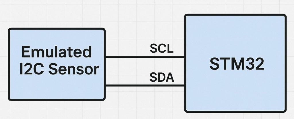
I2C (Inter-Integrated Circuit) is a widely-used, two-wire serial communication protocol designed for short-distance communication between integrated circuits. It consists of two lines:
- SCL (Serial Clock Line): Provides the clock signal generated by the master.
- SDA (Serial Data Line): Used for bidirectional data transfer.
I2C supports multiple slave devices on the same bus, each identified by a unique 7-bit or 10-bit address. Sensors such as accelerometers, gyroscopes, temperature sensors, and EEPROMs commonly use I2C for data communication.
Emulating such sensors on an STM32 microcontroller enables a developer to mimic a full I2C device’s response behavior, including address recognition, data transfers, and register-level interactions. This is not only useful for embedded systems testing but also for demonstrating how sensors operate internally.
Hardware Requirements
- STM32 Microcontroller:
- Select an STM32 MCU that supports I2C hardware in slave mode (e.g., STM32F1, F4, L4, H7 series).
- It should have sufficient I/O capabilities, clock speed, and available peripherals to handle I2C traffic and manage emulated sensor logic.
- I2C Bus Compatibility:
- The STM32 must be physically connected to the I2C master via two GPIOs configured for I2C: one for SCL and one for SDA.
- These lines should support open-drain configuration, as per the I2C specification.
- Pull-up Resistors:
- Both SCL and SDA lines must be pulled up to the supply voltage (typically 3.3V or 5V) using appropriate resistors (usually 4.7 kΩ to 10 kΩ).
- The STM32 and the master device must share a common ground reference.
- Clock Synchronization:
- The STM32, when acting as an I2C slave, must be able to synchronize to the master’s clock.
- The slave cannot drive the clock line but must respond in synchrony with it.
- Electrical Considerations:
- Ensure voltage level compatibility between the master and STM32. If the STM32 operates at 3.3V and the master at 5V, use level shifters or ensure the master supports 3.3V I2C logic levels.
- Pay attention to I2C bus capacitance, especially when connecting multiple devices or using long wires.
Functional Requirements of an Emulated Sensor
To effectively emulate an I2C sensor, the STM32 must mimic:
- I2C Address Recognition: Responding only to its assigned address.
- Register Map Emulation: Simulating internal registers, such as configuration registers, data output registers, and identification registers like
WHO_AM_I. - Read/Write Behavior: Supporting correct behavior when the master reads or writes to specific registers.
- Timing Constraints: Responding within required I2C bus timing limits to avoid errors.
- Optional Features:
- Implementing repeated starts, clock stretching (if needed and supported), or even simulating interrupt outputs via GPIO for “data ready” signals.
Use Cases and Benefits
- Firmware Development:
- Test I2C master firmware without needing physical sensors.
- Verify register-level communication handling and error recovery logic.
- Education and Demonstration:
- Teach I2C communication by showing both master and slave implementations.
- Use in lab experiments where replicating sensor output can be controlled manually.
- Debugging and Validation:
- Emulate sensors to reproduce specific edge cases or faults (e.g., constant readings, corrupted data).
- Validate system behavior when the sensor is absent or responds incorrectly.
- System Simulation:
- Build virtual hardware prototypes.
- Create simulation environments that replicate production systems.
2. I2C Slave Configuration:
We start off by creating new project as follows:
Open STM32CubeIDE after selecting the workspace and create new project as following:

Select the MCU:

Give the project a name:
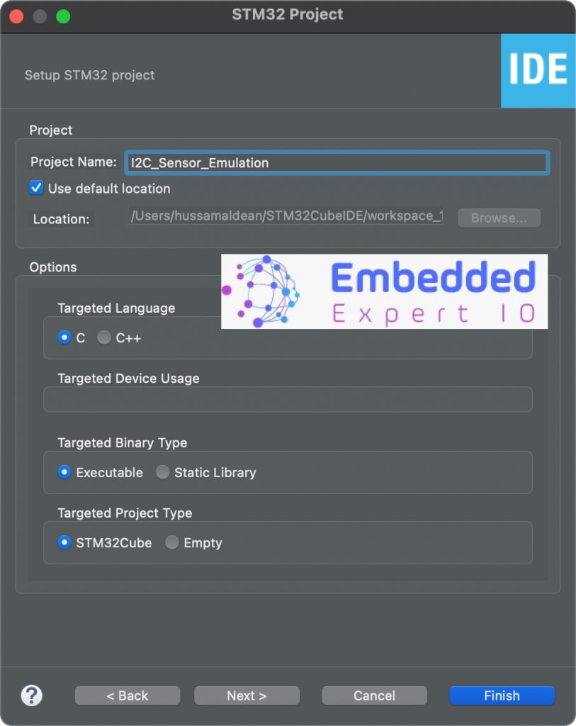
Make sure the Targeted Project Type is STM32Cube, Language is C and binary type is Executable.
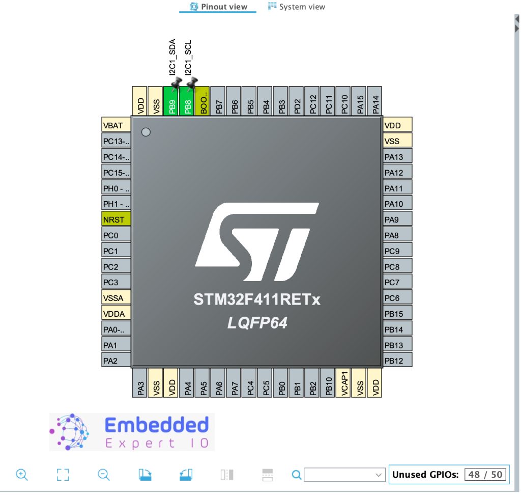
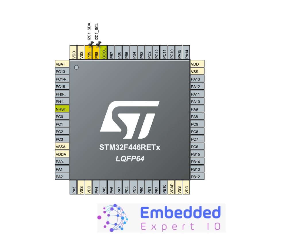
After that, set PB8 and PB9 for I2C1 or I2C3, here we shall use I2C1 as following:
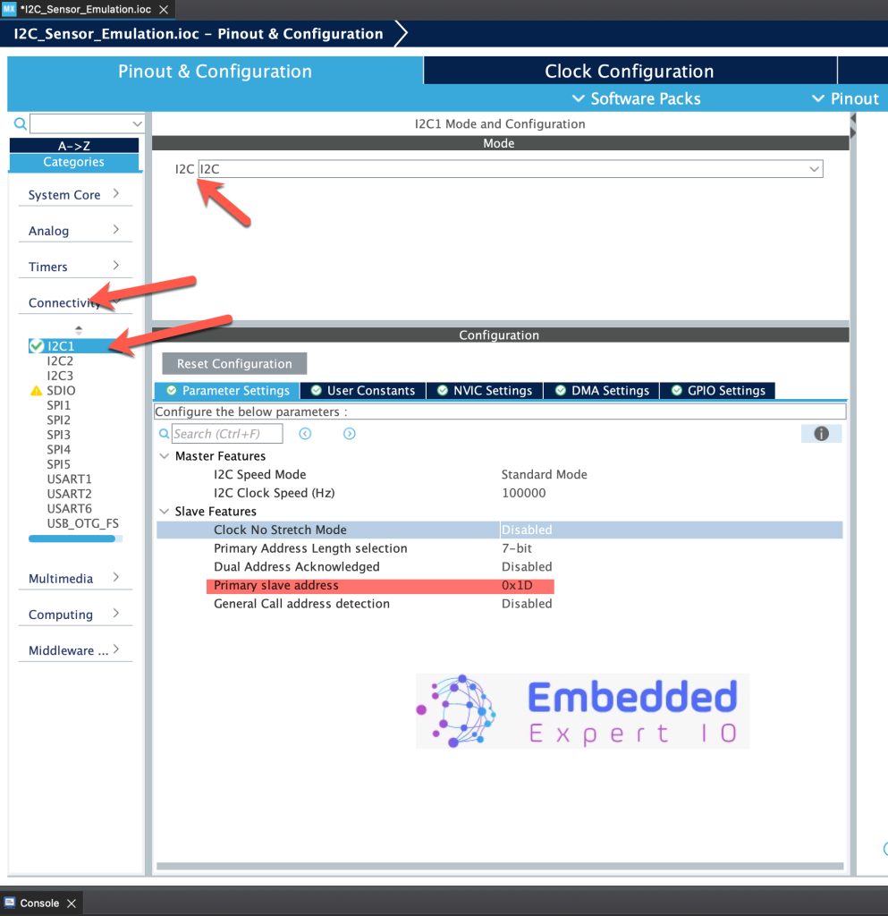
Next, we shall configure I2C as follows:
- Set I2C mode to I2C.
- Set Primary slave address to 0x1D.
- Leave the rest of parameters as is.
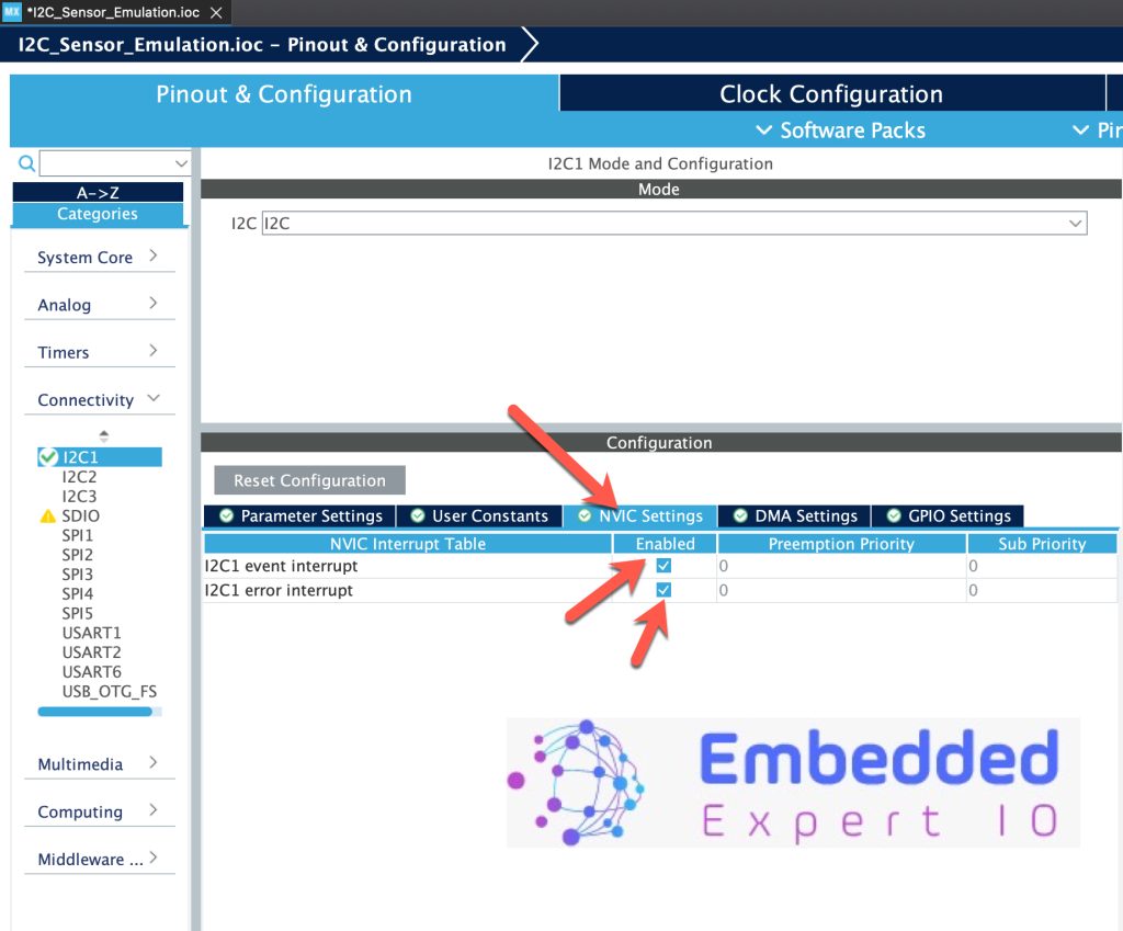
Next, Enable interrupt for i2c as follows:
- I2C1 event interrupt.
- I2C1 error interrupt.
Next, from GPIO Settings, enable Pullup as follows:
Thats all for the slave configuration. Save the project and this will generate the code.
3. Master Configuration:
After selecting the MCU, give the project a name:
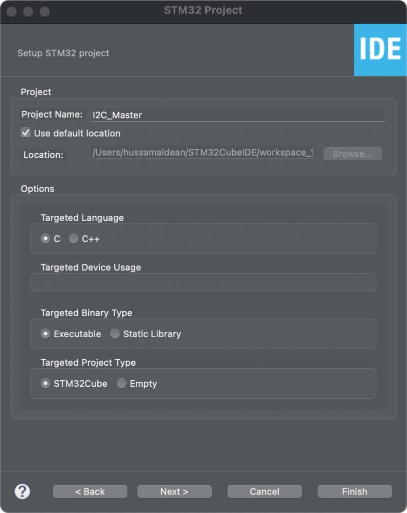
Make sure the Targeted Project Type is STM32Cube, Language is C and binary type is Executable.
After that, set PB8 and PB9 for I2C1 or I2C3, here we shall use I2C1 as following:
Next, configure the I2C as follows:
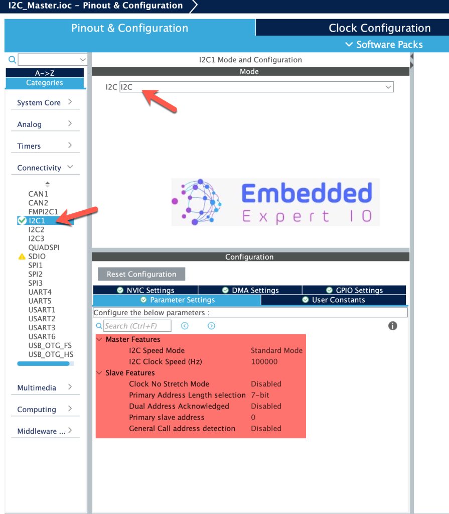
Leave everything as default since we are planning to use polling mode to read from salve I2C.
Next, enable USART2 to use with printf later in the guide. To enable USART:
Leave everything as is.
Thats all for the Master configuration. Save the project and this will generate the code.
4. Connection:
The connection as follows:
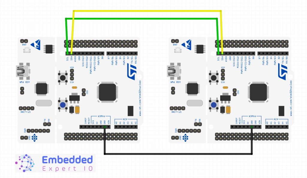
| Pin | STM32F4 Master | STM32F4 Slave |
| P8 | PB8 | PB8 |
| PB9 | PB9 | PB9 |
| GND | GND | GND |
Stay tuned for part 2 for communication.
Happy coding 😉
Add Comment