In this guide, we shall use MicroPython on the STM32F411 Nucleo board to blink two LEDs connected to PA0 and PA1. The LEDs will toggle at different time intervals using utime for non-blocking periodic execution inside the main loop.
In this guide, we shall cover the following:
- Introduction.
- Hardware setup.
- Firmware development.
- Results.
1. Introduction:
Periodic task execution is a fundamental concept in embedded systems development. It allows certain actions to be performed at regular time intervals, such as blinking LEDs, updating sensor readings, communicating over serial interfaces, or controlling motors. In traditional embedded programming, this is often achieved using hardware timers or interrupt-based mechanisms. However, in many applications, especially simple ones, it is easier and more flexible to implement periodic tasks using software timing within the main loop.
MicroPython is a lightweight and efficient implementation of Python designed for microcontrollers like the STM32F411 Nucleo board. It provides useful modules such as utime that allow developers to perform non-blocking timing operations without relying on hardware interrupts. This makes the code simpler, easier to understand, and safer when dealing with functions that should not be called from interrupt context (such as print statements or communication functions).
In this guide, we shall use MicroPython on the STM32F411 Nucleo board to demonstrate how to blink two LEDs connected to GPIO pins PA0 and PA1. Each LED will toggle independently at a different time interval. The first LED will blink every 1 second, while the second LED will blink every 500 milliseconds. This will be achieved using the utimemodule and the ticks_ms() function to track elapsed time in a non-blocking way within the main loop. This method is efficient, easy to extend for multiple tasks, and suitable for many real-world embedded projects.
2. Hardware Setup:
The connection of the two LEDs as following:
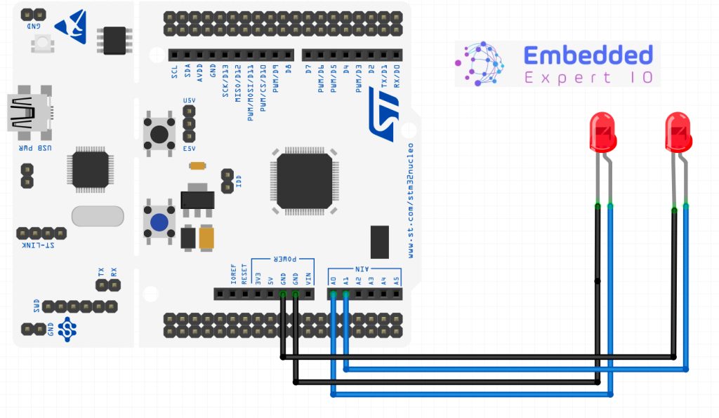
Note: It is recommended to use 220 Ohm current limiting resistors. However, in this application, they have been omitted for simplicity and short running time for LEDs and MCU.
3. Firmware Development:
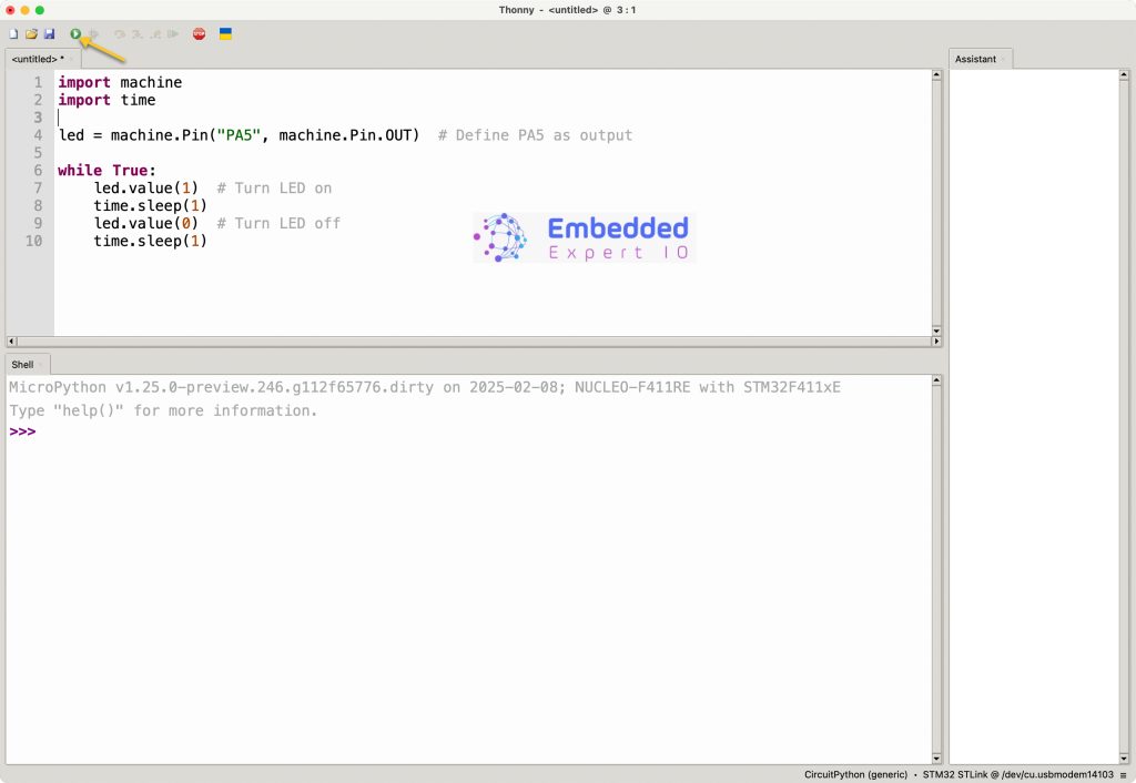
First, we need to configure Thonny to work with STM32F411 Nucleo-64. Please refer to this guide for how to install and configure Thonny.
After the setup has been completed, we start a new project.
Start by importing the following:
from machine import Pin
import utime
Declare the LED pins as following:
# Define LEDs
led1 = Pin('PA0', Pin.OUT)  # LED 1 on PA0
led2 = Pin('PA1', Pin.OUT)  # LED 2 on PA1
Next, variable to hold the blinking intervals as following:
# Define blink intervals (ms)
interval1 = 1000  # 1 second
interval2 = 500   # 0.5 second
Next variable to hold the timer since the last LED has been toggled:
# Store last toggle times
last_time1 = utime.ticks_ms()
last_time2 = utime.ticks_ms()
Next, declare variables to store the toggle state:
#Toggle State
toggle1=0
toggle2=0
Declare while loop as following:
while True:

    #get the current time in milliseconds
    now = utime.ticks_ms()

    # Handle LED1 (PA0)
    if utime.ticks_diff(now, last_time1) >= interval1:
        toggle1 = not toggle1
        last_time1 = now
        led1.value(toggle1)

    # Handle LED2 (PA1)
    if utime.ticks_diff(now, last_time2) >= interval2:
        toggle2 = not toggle2
        last_time2 = now
        led2.value(toggle2)
The concept as following:
- Get the current time in milliseconds.
- Calculate the time difference between the current time and the last time the led has been toggled, if the time is larger.
- Store the current time into the last time the led blink.
- Invert the toggle state.
- Write the new value to the pin.
Thats all for the firmware.
Click on run as following:
4. Results:
Notice the two LEDs. They are blinking as expected.
Happy coding 😉
Add Comment