
After we have learnt how to compile and flash the board with micropython, in this guide, we shall use micropython to control on the board LED. This guide shall cover the basic of GPIO control in output mode.
In this guide, we shall cover the following:
- Getting on the board LED.
- Configuring Thonny
- Developing the driver.
- Results.
1. Getting on the Board LED:
Since the STM32F411RE Nucleo-64 has built-in user LED which is LD2.
First, we need to know which pin is connected to LD2. In order to find this, we need to get UM1724 for Nucleo-64. You can get the manual from here.
From the manual:
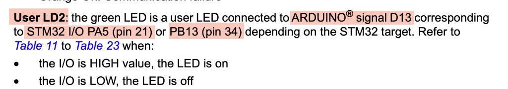
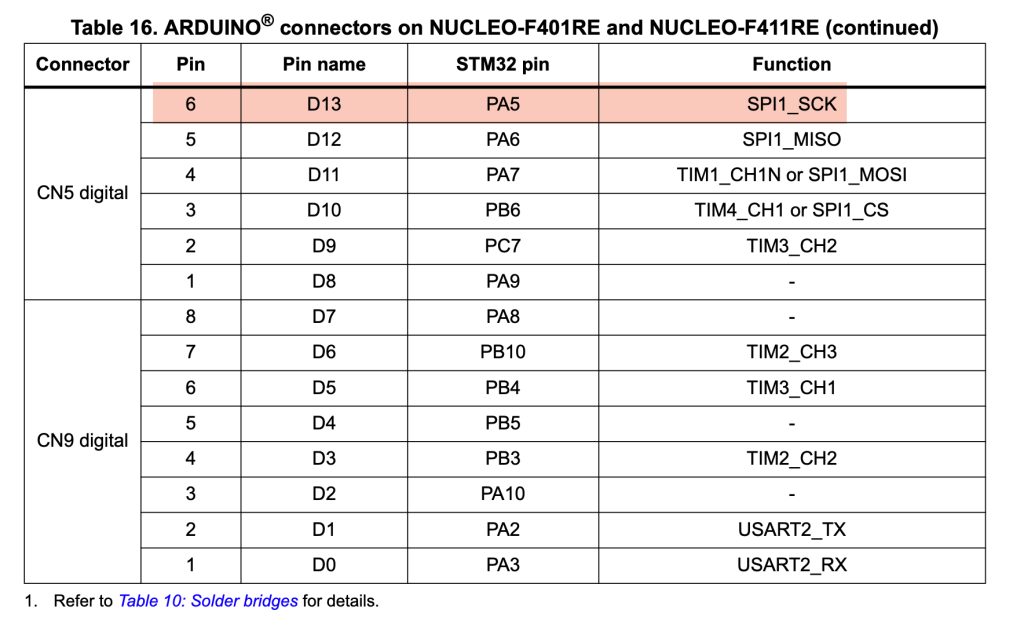
Hence, we can see that LD2 is connected to PA5.
2. Configure Thonny.
After the LED pin has been identified, we need to install Thonny.
To get Thonny, you can download it from here.
After you downloaded Thonny and install it. Open it.
Next, we shall configure it.
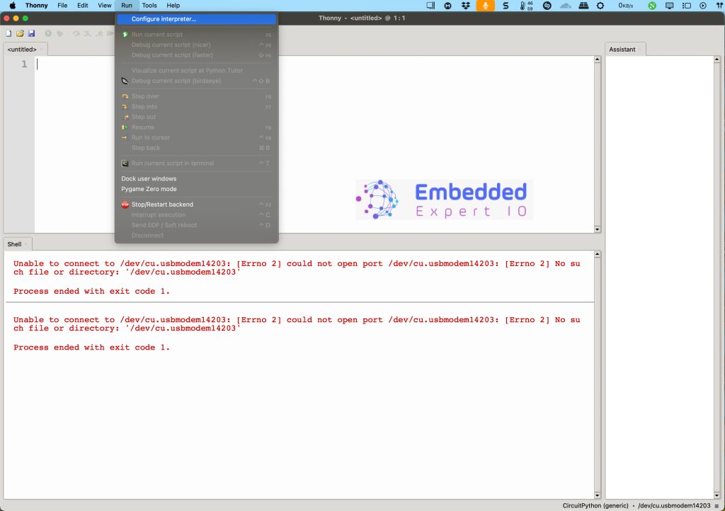
From menu, select run and then Configure Interpreter as following:
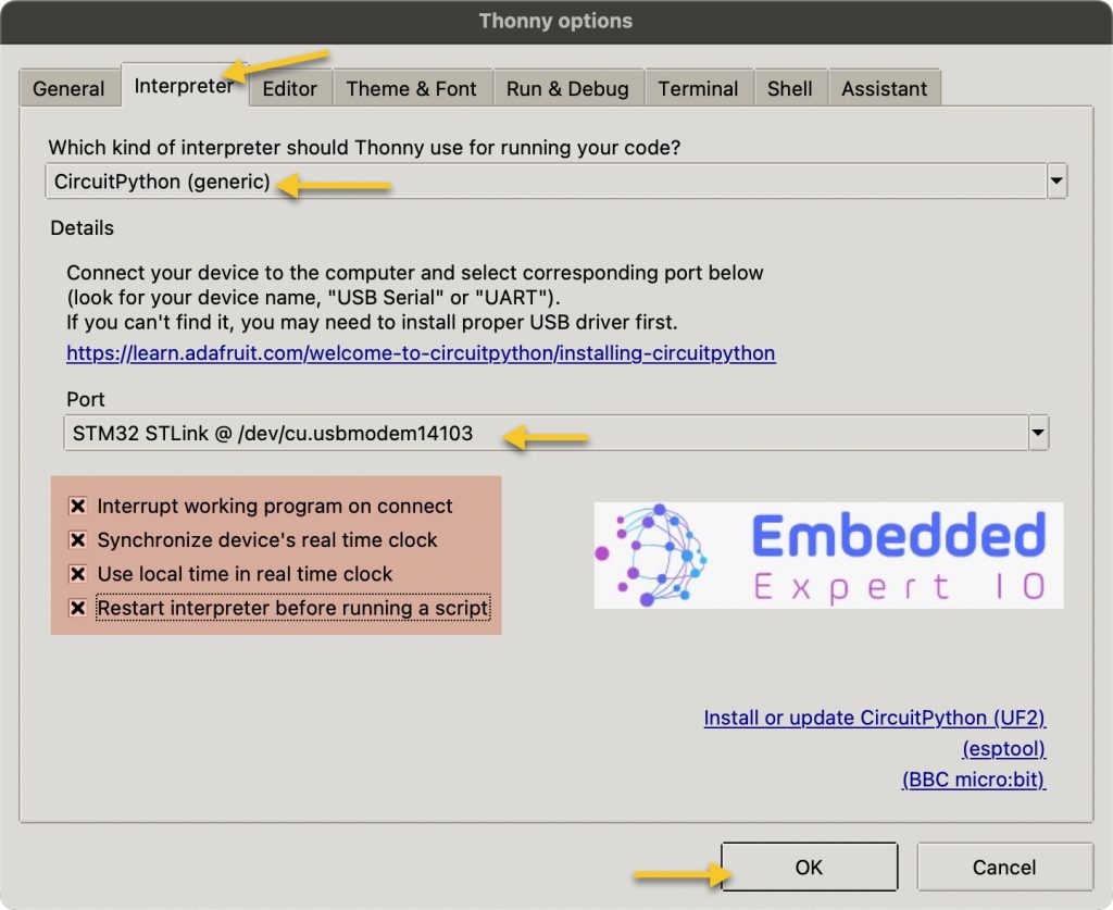
After that, select interpreter and configure it as following:
- Interpreter as CircuitPython.
- Port, select STM32 ST-Link.
- Make sure the last four options are selected.
- Click on OK.
After clicking on OK, the shell shall show this:
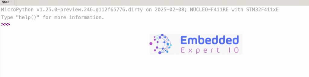
Thats all for the configuration.
3. Developing the Driver:
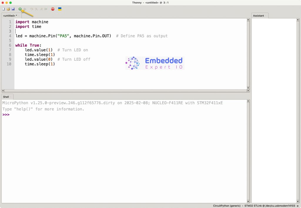
In the top window where you can type your script, we start developing the driver.
Start of by importing time and machine:
import machine
import time
The machine library will allow us to control STM32 peripherals like GPIO, I2C ect.
The time library will allow us to generate timing event like delay etc.
Next, define led as following:
led = machine.Pin("PA5", machine.Pin.OUT) # Define PA5 as outputmachine.Pin will set specific pint to either input or output.
Since the LED is output, we can set it as machine.Pin.Out.
Since the led is defined, we can control it in the while loop as following:
while True:
    led.value(1)  # Turn LED on
    time.sleep(1)
    led.value(0)  # Turn LED off
    time.sleep(1)
Note: In python, the body of while loop is 1 tab distance from it.
In the while loop, we can set led value using led.value function as following:
- Set to 1 will set the pin to high.
- Set to 0 will set the pin to low.
time.sleep(1) will delay by 1 second.
Thats all for the driver.
Click on run as following:
4. Results:
Happy coding 😉
Add Comment