
In this guide, we shall see how to receive data using UART in LIN configuration.
In this guide, we shall cover the following:
- UART6 configuration.
- Modification to source and header file.
- Developing the receiver driver.
- Hardware connection
- Results.
1. UART6 Configuration:
Since STM32F411RE Nucleo has three uarts as following:
- USART1 which is already used by the transmitter.
- USART2 which is used by on board ST-Link V2.
- UART6 which will be the receiver of the data over LIN.
From the previous part here, open the .ioc file as following:
Once the CubeMX window is opened, from connectivity, select UART6 and set it to LIN as following:
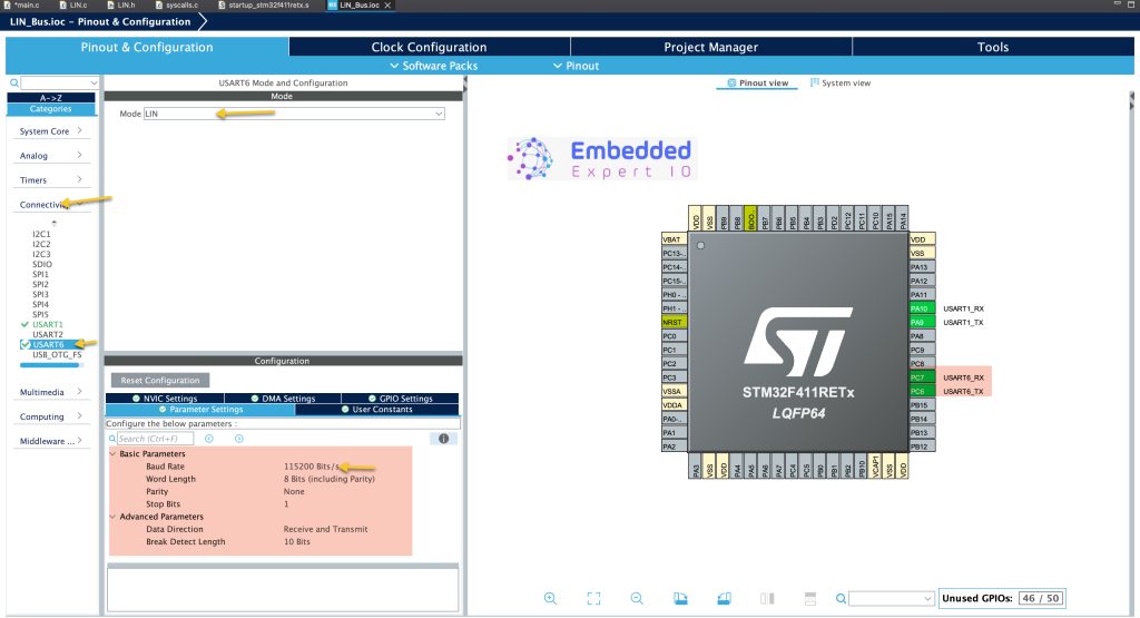
This will automatically enabled PC6 and PC7 for UART communication.
Note: Make sure to match the baudrate in USART1 with the one in UART6.
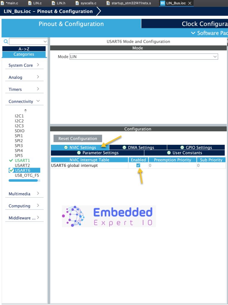
Also, from NVIC Setting, enable UART6 global interrupt as following:
Thats all for the UART6 configuration.
Save the project this will generate the new code.
2. Modification to Source and Header File:
Open LIN.c source file and remove the static from the check sum to become like this:
uint8_t checksum_Calc (uint8_t PID, uint8_t *data, int size)
Save the source file.
Next, open the header file and add the check_sum to the header file as following:
uint8_t checksum_Calc (uint8_t PID, uint8_t *data, int size);
Hence, the new header file will be as following:
#ifndef INC_LIN_H_
#define INC_LIN_H_

#include "main.h"
#include "stdint.h"

uint8_t LIN_Transmit_Data(uint8_t ID, uint8_t *data, uint16_t len);
uint8_t checksum_Calc (uint8_t PID, uint8_t *data, int size);

#endif /* INC_LIN_H_ */
Save the header file.
That’s all for the modification.
3. Developing the Receiver Driver:
In main.c, we start by including the stdlib header file which will allow us to generate random numbers as following:
#include "stdlib.h"
Next, in user code begin PV, declare the following array:
uint8_t LINDataRX[20];
This array shall hold the entire data packet from the LIN bus.
Next, the array to hold the actual received data:
uint8_t LINDataReceived[8];
Next, some auxiliary variables needed as following:
- Number of bytes received
int numDataBytes = 0;
- The ID:
uint8_t ID = 0;
- Is data valid:
int isDataValid = 0;
Next, a variable to store the previous ticks which will be used to store the ticks for sending purposes as following:
uint32_t previousTicks=0;
Next, in user code begin 2 in the main function we shall fill the sending array with random data as following:
for (int i=0; i<8; i++)
	{
		LINData[i] = rand() % 255;
	}
This will fill the array with random data.
Next, we shall start UART6 to receive data in interrupt mode until IDLE line is detected as following:
HAL_UARTEx_ReceiveToIdle_IT(&huart6, LINDataRX, 20);
This will trigger interrupt either the full 20 characters have received or IDLE line is detected. We know the maximum length for the data is 12 byte, but we gave extra bytes just in case.
In user code begin 3 in while 1 loop:
First, check if there is a valid data as following:
if(isDataValid==1)
	  {
		  for (int i=0; i<numDataBytes; i++)
		  {
			  LINDataReceived[i] = LINDataRX[i+3];
		  }
		  isDataValid = 0;
	  }
If yes, fill the Received buffer with the actual data and reset isDataValided back to 0.
Next, we shall transmit the data each 300ms as following:
	  if(HAL_GetTick()-previousTicks>300)
	  {

		LIN_Transmit_Data(0x34, LINData, 8);
		for (int i=0; i<8; i++)
		{
			LINData[i] = rand() % 255;
		}
		previousTicks=HAL_GetTick();
	  }
This function will allow us to send the data without using any delays.
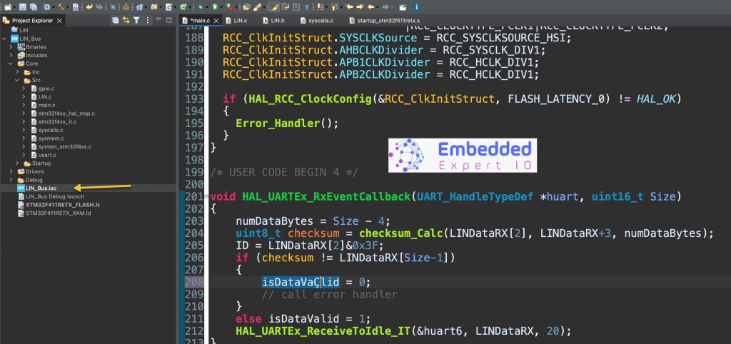
In user code begin 4 at near the end of main.c:
void HAL_UARTEx_RxEventCallback(UART_HandleTypeDef *huart, uint16_t Size)
{
	numDataBytes = Size - 4;
	uint8_t checksum = checksum_Calc(LINDataRX[2], LINDataRX+3, numDataBytes);
	ID = LINDataRX[2]&0x3F;
	if (checksum != LINDataRX[Size-1])
	{
		isDataVaÇlid = 0;
		// call error handler
	}
	else isDataValid = 1;
	HAL_UARTEx_ReceiveToIdle_IT(&huart6, LINDataRX, 20);
}
The function:
void HAL_UARTEx_RxEventCallback(UART_HandleTypeDef *huart, uint16_t Size) will be called every time when either 20 bytes have been received or IDL line has been detected.
Once the function is called, first we get the number of data bytes as following:
numDataBytes = Size - 4;
Then we shall calculate the check sum as following:
uint8_t checksum = checksum_Calc(LINDataRX[2], LINDataRX+3, numDataBytes);
Since the checksum takes first the PID which is always at 3rd position of the array (index 2), the actual data which start at the fourth position and the data length.
Next, calculate the ID as following:
ID = LINDataRX[2]&0x3F;
This will give us the ID of the data packet.
Next, check if the checksum is matched or not, if matched, set isDataValid to 1 and if it is not, reset it to zero and restart the UART reception until IDLE in interrupt mode as following:
if (checksum != LINDataRX[Size-1])
	{
		isDataValid = 0;
		// call error handler
	}
	else isDataValid = 1;
	HAL_UARTEx_ReceiveToIdle_IT(&huart6, LINDataRX, 20);
Thats all for the main.c
Save the project, build it and run it in debugging mode on your STM32F4 board.

4. Hardware Connection:
The connection is as simple as connecting PC7 to PA9 using jumper wire as following:
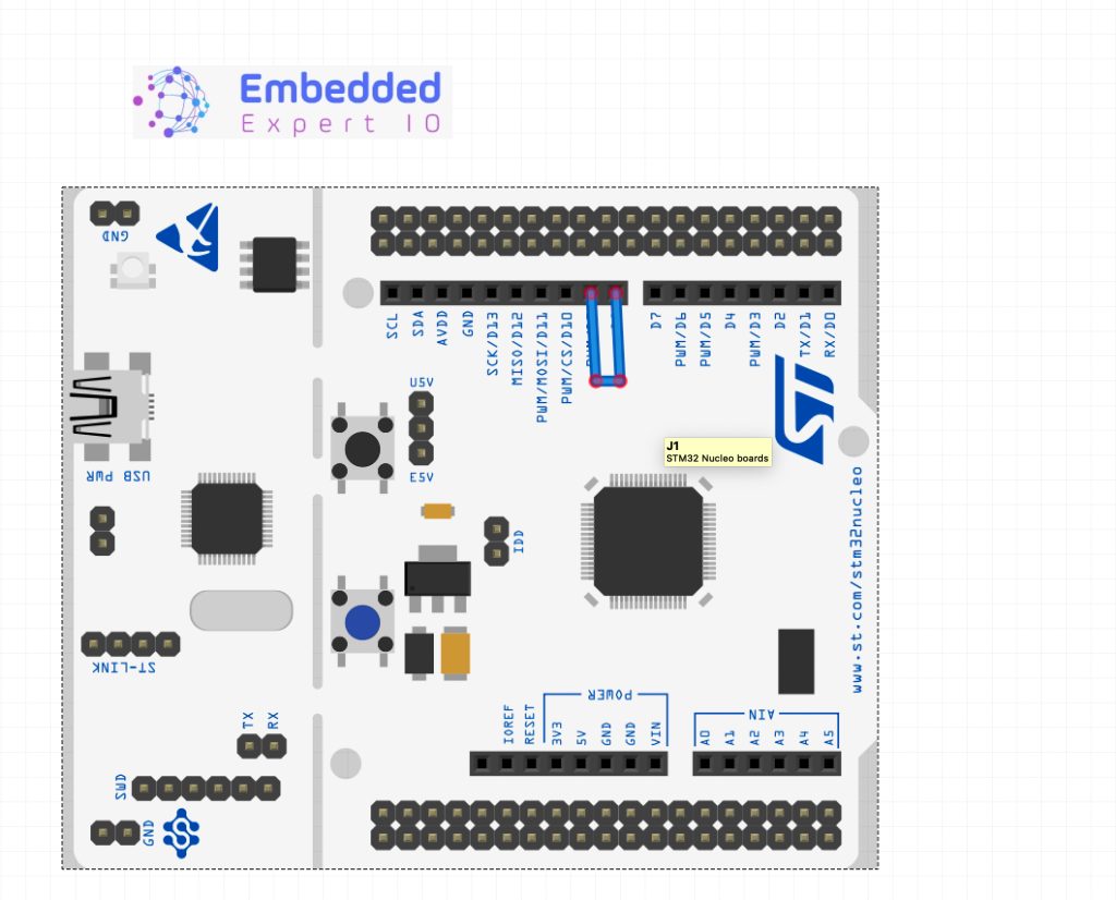
Simply, connect a wire from D8 to D9 of the arduino header.
5. Results:
Add both LINData and LINDataReceived to live expression and you should get the following:
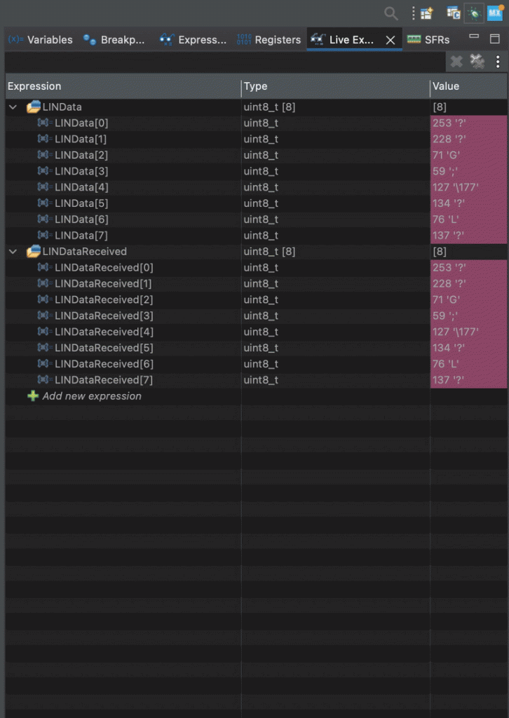
As you can see, the data do match.
Happy coding 😉
Add Comment