In part 2 of LIN guide, we shall start transmitting data over LIN bus and decode them using either oscilloscope or logic analyzer.
In this guide, we shall cover the following:
- Creating source and header files.
- Developing the header file.
- Developing the source file.
- Logic Analyzer connection
- Testing the driver.
- Results.
3. Creating Source and Header Files:
After the project has been generated, right click on src folder and add new source file as following:
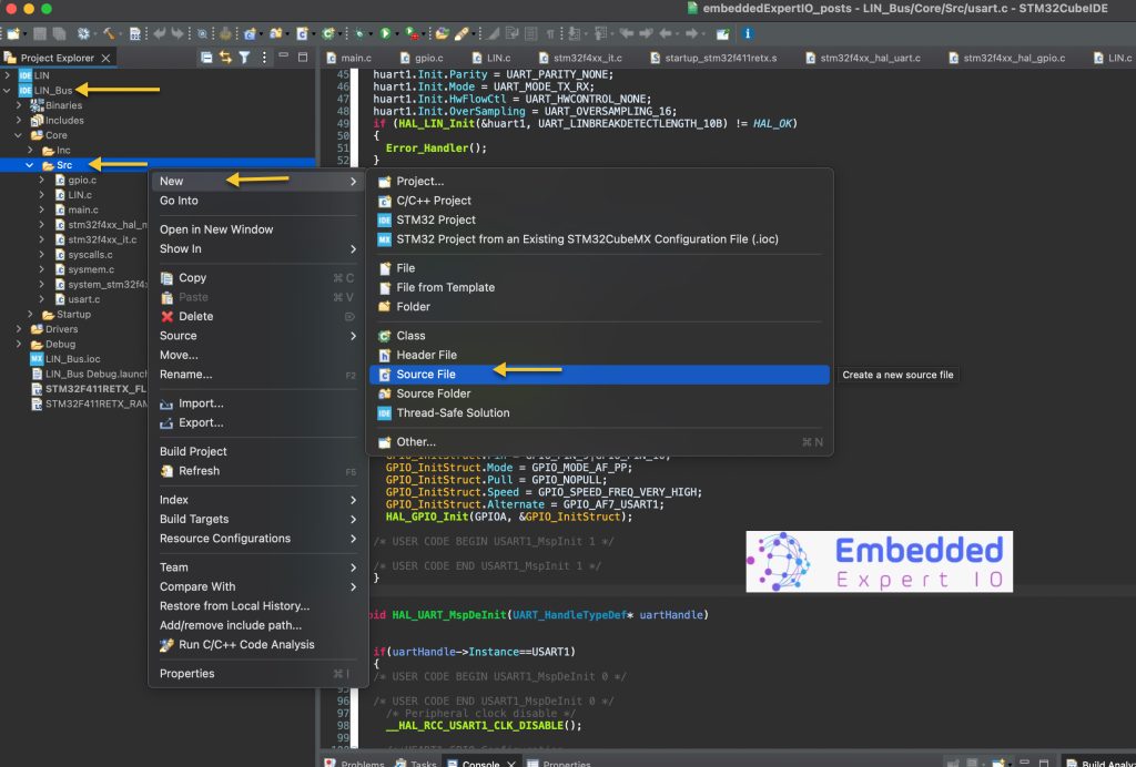
Name the source file as LIN.c as following (here, it is already created):
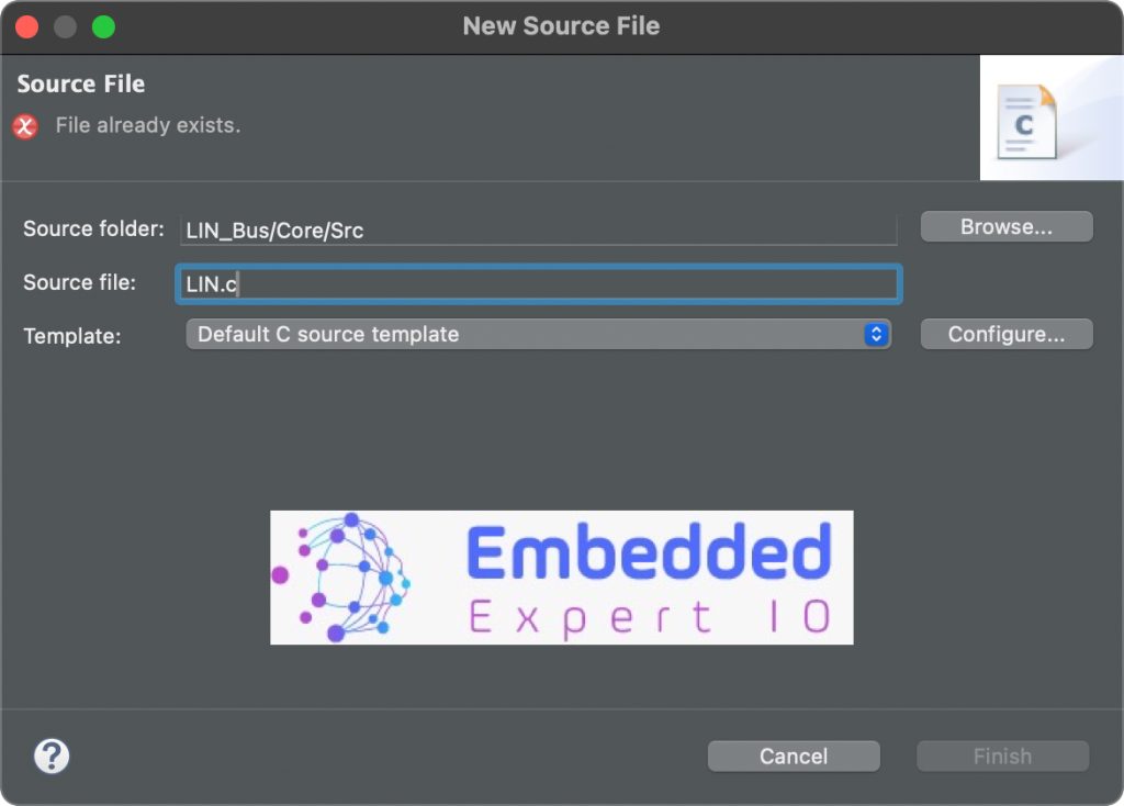
In similar manner, the create new header file with name of LIN.h
Thats all for creating header and source file.
4. Developing the Header File:
In the header file, include the required header files as following:
#include "main.h"
#include "stdint.h"
Declare the following function:
uint8_t LIN_Transmit_Data(uint8_t ID, uint8_t *data, uint16_t len);
The function shall transmit data over LIN bus.
The function shall take the following parameters:
- ID which is the identification of the node that shall receive the message.
- Pointer of the data to be transmitted.
- Length of the data to be transmitted.
The function shall return 0 in case of success and -1 in case of failure.
Thats all for the header file.
5. Developing the Source File:
Next, open LIN.c source file.
We start by including the following headers file:
#include "LIN.h"
#include "usart.h"
Then we shall declare the following function to calculate the check sum of the message as following:
static uint8_t checksum_Calc (uint8_t PID, uint8_t *data, int size)
{
	uint8_t buffer[size+2];
	uint16_t sum = 0;
	buffer[0] = PID;
	for (int i=0; i<size; i++)
	{
		buffer[i+1] = data[i];
	}

	for (int i=0; i<size+1; i++)
	{
		sum += buffer[i];
		if (sum>0xff) sum = sum-0xFF;
	}

	sum = 0xFF-sum;
	return sum;
}
The function is static since it is related to this source file and not another one.
Also, the function to calculate the protected ID as following:
static uint8_t pid_Calc (uint8_t ID)
{
	uint8_t IDBuf[6];
	for (int i=0; i<6; i++)
	{
		IDBuf[i] = (ID>>i)&0x01;
	}
	uint8_t P0 = (IDBuf[0]^IDBuf[1]^IDBuf[2]^IDBuf[4])&0x01;
	uint8_t P1 = ~((IDBuf[1]^IDBuf[3]^IDBuf[4]^IDBuf[5])&0x01);
	ID = ID | (P0<<6) | (P1<<7);
	return ID;
}
Next a function that allow us to send single byte over LIN bus as following:
static void LIN_SendByte(uint8_t data)
{
    while (!(USART1->SR & USART_SR_TXE)); // Wait until TX is empty
    USART1->DR = data;                    // Send data
}
The function shall take uint8_t data argument and return nothing.
The function is the same as sending data over uart using register level.
Next, the main function:
uint8_t LIN_Transmit_Data(uint8_t ID, uint8_t *data, uint16_t len)
{
	if (ID > 0x3F) return -1;

	if(len>8) return -1;


	uint8_t PID=pid_Calc(ID);

	uint8_t checkSum=checksum_Calc(PID,data,len);


	USART1->CR1 |= USART_CR1_SBK;  // Send Break

	LIN_SendByte(0x55); //sync field
	LIN_SendByte(PID); //PID
	for (int i=0;i<len;i++)
	{
		LIN_SendByte(data[i]);
	}
	LIN_SendByte(checkSum);

	return 0;

}
In order to send data over LIN bus, we need first to arrange the data in certain way.
First, check if the ID is bigger than 0x3F then it is not valid and return -1.
Also, if the data length is more than 8 byte, return -1 since the maximum is 8 byte.
Once the conditions are met, calculate the PID from the passed ID.
Do checksum to the message to be sent by including also the data to be transmitted and the length of the data.
Once the data has been structured correctly, we start the transmission by sending the Break signal as following:
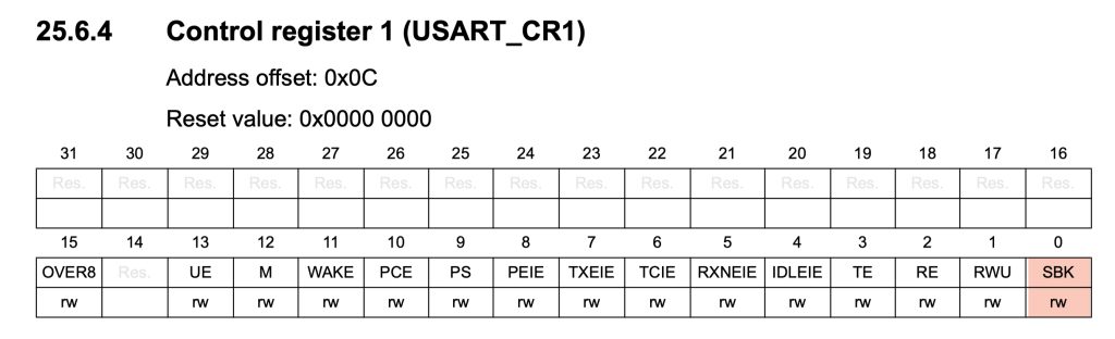
USART1->CR1 |= USART_CR1_SBK; // Send Break
Then transmit the sync field as following:
LIN_SendByte(0x55); //sync field
Then the PID:
LIN_SendByte(PID); //PID
Next transmit the data:
for (int i=0;i<len;i++)
{
  LIN_SendByte(data[i]);
}
Finally, send the checksum as following:
LIN_SendByte(checkSum);
Return 0 to indicate the success.
return 0;
Thats all for developing the source file.
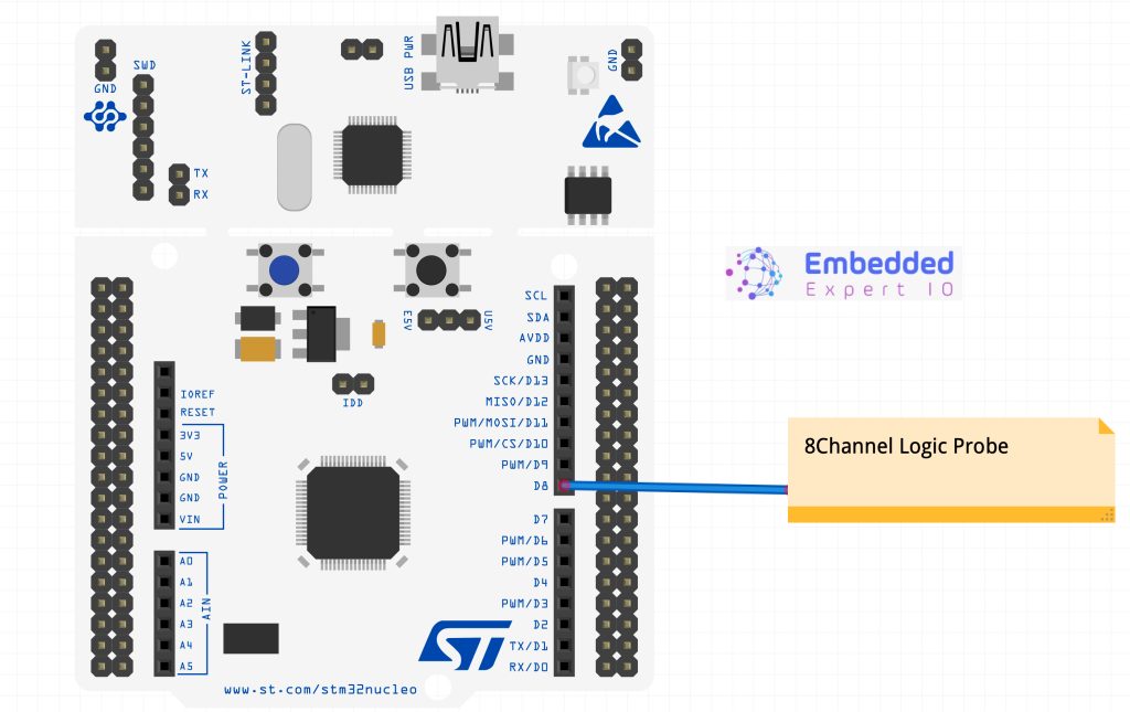
6. Connecting the Logic Analyzer:
You can connect CH0 of the logic analyzer to the PA9 (D8 of Arduino Uno pins) as following:
7. Testing the Driver:
In main.c file.
In user code begin includes, include LIN.h as following:
#include "LIN.h"
In user code begin PV, declare a buffer to hold the data to be transmitted as following:
uint8_t LINData[8];
In user code begin 2 in main function, fill the buffer with data as following:
	for (int i=0; i<8; i++)
	{
		LINData[i+2] = i;
	}
In user code begin 3 in while 1 loop, transmit the data with ID 0x34 as following:
LIN_Transmit_Data(0x34, LINData, 8);
Delay by amount of 100ms as following:
HAL_Delay(100);
Save the project, build it and run it on your STM32F4 board.

8. Results:
Here, I am using oscilloscope to decode the data and you should get the following:
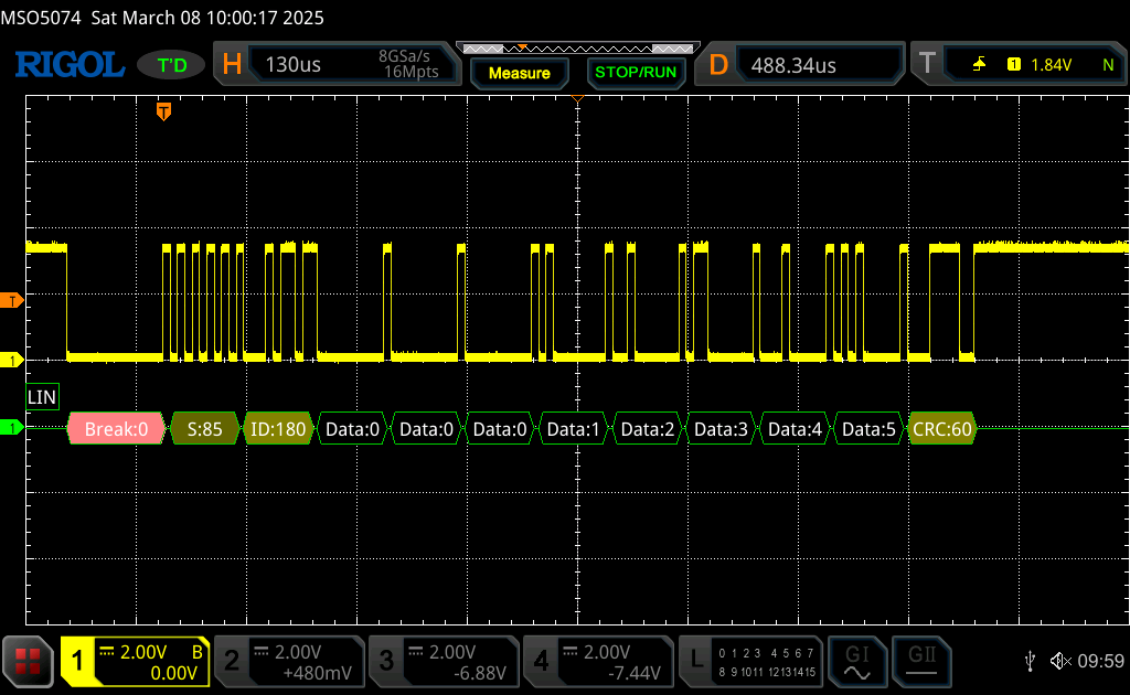
Everything look great and we have successfully transmitted data over LIN bus.
In part 3, we shall start receiving data over LIN bus
Stay tuned and happy coding 😉
2 Comments
Kindly Change as Part-2, if my understanding is correct, HSR-Rao
Yes. You are correct.
Fixed.
Add Comment