
In this guide, we shall take a look at the I2C bus and how to configure the i2c of STM32H5 using STM32CubeMX.
In this guide, we shall cover the following:
- I2C bus.
- DS3231 module connection.
- STM32CubeIDE configuration.
- Read and write to I2C slave.
- Results.
1. I2C Protocol:
I2C or Inter Integrated Circuit is type of synchronous serial communication that capable to communicate with up to 127 slave devices as show in figure below.
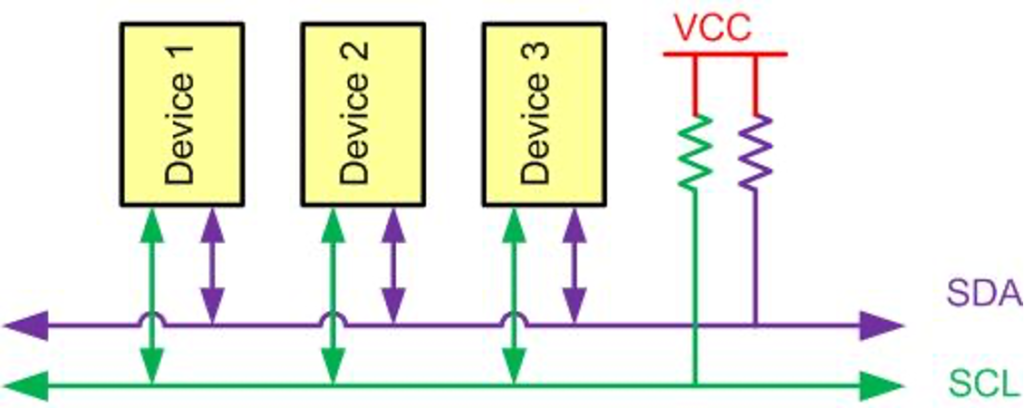
Like UART communication, I2C only uses two wires to transmit data between devices:
- SDA (Serial Data): The line for the master and slave to send and receive data.
- SCL (Serial Clock): The line that carries the clock signal.
1.2: HOW I2C WORKS
With I2C, data is transferred in messages. Messages are broken up into frames of data. Each message has an address frame that contains the binary address of the slave, and one or more data frames that contain the data being transmitted. The message also includes start and stop conditions, read/write bits, and ACK/NACK bits between each data frame:
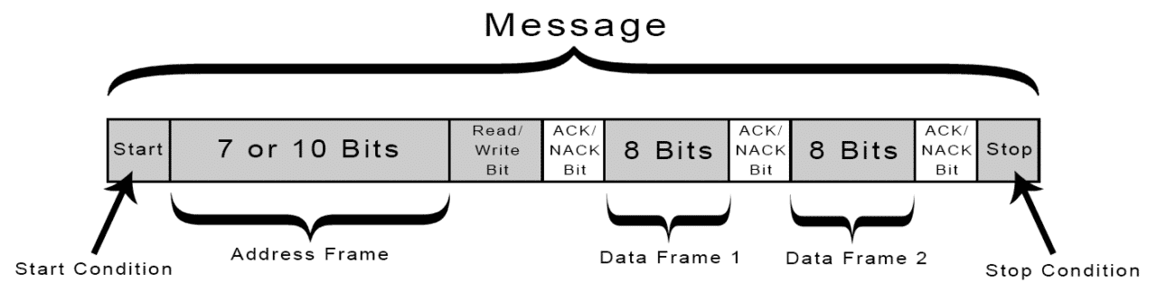
Start Condition: The SDA line switches from a high voltage level to a low voltage level before the SCL line switches from high to low.
Stop Condition: The SDA line switches from a low voltage level to a high voltage level after the SCL line switches from low to high.
Address Frame: A 7 or 10 bit sequence unique to each slave that identifies the slave when the master wants to talk to it.
Read/Write Bit: A single bit specifying whether the master is sending data to the slave (low voltage level) or requesting data from it (high voltage level).
ACK/NACK Bit: Each frame in a message is followed by an acknowledge/no-acknowledge bit. If an address frame or data frame was successfully received, an ACK bit is returned to the sender from the receiving device.
For more information and detailed explanations refer to this NXP documentation (here).
2. DS3231 Module Connection:
Since this guide uses DS3231 module as shown in picture below:
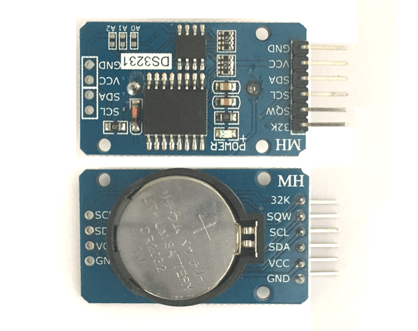
This module has the required parts to make I2C working like the external Pull-up resistors etc.
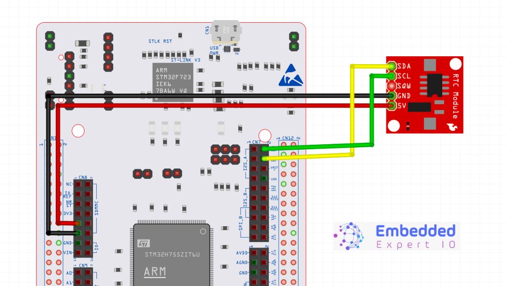
Hence, the connection as following:
3. STM32CubeIDE Configuration:
We start off by creating a new project with name of i2c_fullduplex as following:
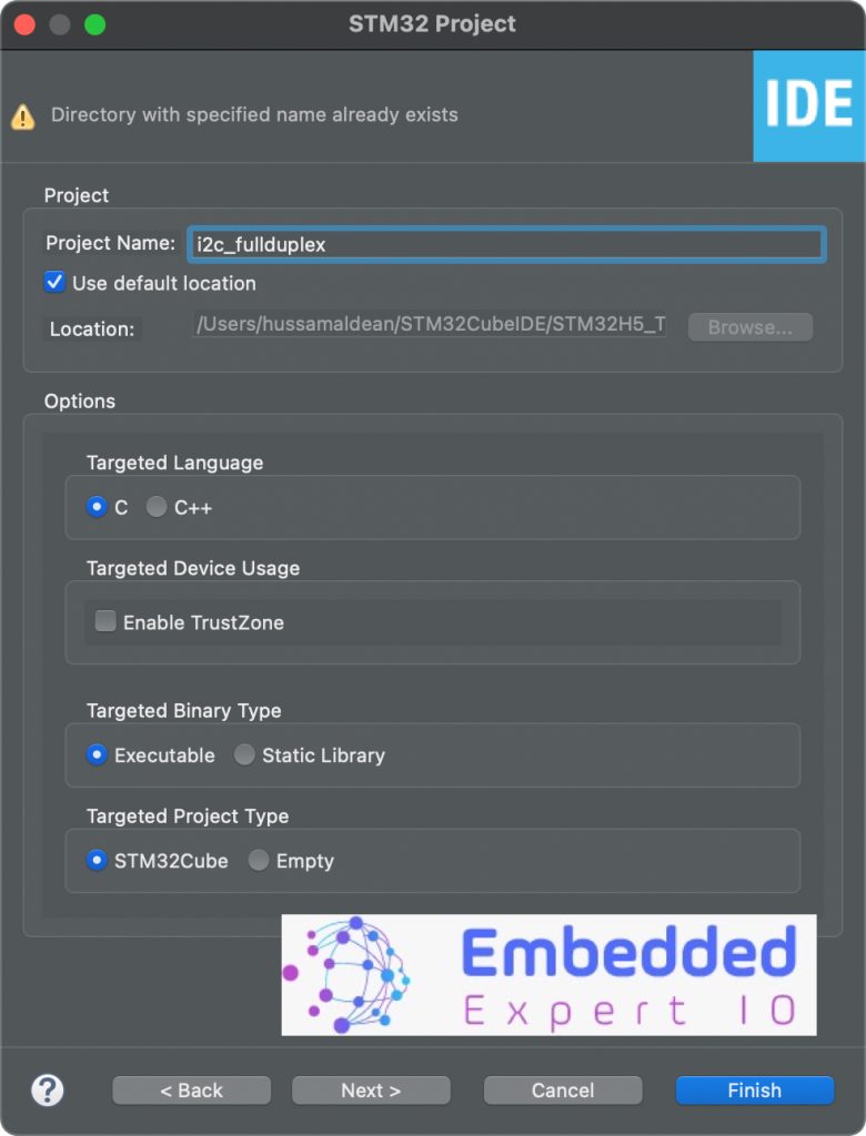
For how to create project using STM32CubeIDE, please follow this guide here.
Next, we need to figure out which pins are connected on D14 and D15 of STM32H563Zi Nucleo-144 development board.
From STM32H563Zi Nucleo-144 user manual (UM3115):
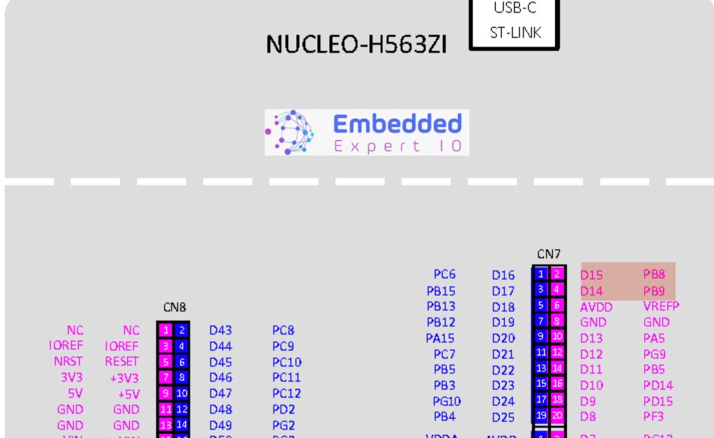
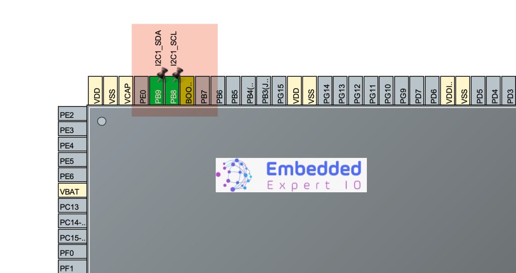
Hence, when STM32CubeMX window appears, set PB8 and PB9 as i2c SCL and i2c SDA as following:
Next from connectivity select I2C1 and enable it as following:
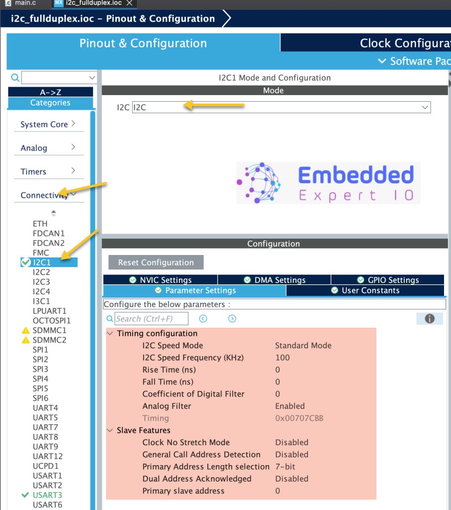
Keep the parameters as default.
Also, enable the UART to print the RTC value. For how to enable the uart, please refer to this guide here.
Save the project and this will generate the code.
4. Read and Write from I2C Slave:
Once the code has been generated, in main.c in user begin includes, include the following header files:
#include "stdio.h"
#include "stdlib.h"
Next, from the datasheet of DS3231, we need to obtain the address
The address can be obtain from read/write figures in the datasheet of the DS3231:
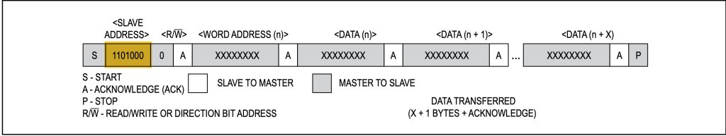
We also need to shift the address to left by for the read/write bit which is bit0 when the master transmit the read/write request.
Hence, the address as following:
In user code begin PD, declare the following:
#define DS3231_Addr (0x68<<1)
In user code begin PV (Private variables), declare a buffer to hold the RTC data as following:
uint8_t rtc_data[3];
In user code begin 0, we shall declare the following two functions:
int __io_putchar(int ch)
{
	HAL_UART_Transmit(&huart3, &ch, 1, 5);

	return ch;
}


int bcd_to_decimal(unsigned char x) {
    return x - 6 * (x >> 4);
}
First function is to use printf with serial port and the second one to convert BCD to decimal format.
In user code begin 3 in while 1 loop:
HAL_I2C_Mem_Read(&hi2c1, DS3231_Addr, 0x00, 0x01, rtc_data, 3, 100);
	  for (int i=0;i<3;i++)
	  {
		  rtc_data[i]=bcd_to_decimal(rtc_data[i]);
	  }
	  printf("RTC DATA H=%d M=%d S=%d\r\n",rtc_data[2],rtc_data[1],rtc_data[0]);
	  if(rtc_data[0]==5)
	  {
		  rtc_data[0]=0x00;
		  rtc_data[1]=(rand() % 5);
		  rtc_data[2]=(rand() % 5);
		  HAL_I2C_Mem_Write(&hi2c1, DS3231_Addr, 0x00, 0x01, rtc_data, 3, 100);
	  }

	  HAL_Delay(200);
First, read the memory from DS3231 0x00 which is the seconds as following:
HAL_I2C_Mem_Read(&hi2c1, DS3231_Addr, 0x00, 0x01, rtc_data, 3, 100);
The function takes 7 parameters as following:
- HandleType of which i2c to be used which is hi2c1 in this case.
- Slave address which is already define as DS3231_Addr.
- Memory location to be read which the seconds register (0x00).
- Size of the address where 0x01 means 1 byte and 0x02 means two bytes.
- The buffer to hold the data to be read which is rtc_data.
- Number of bytes to be read which is 3 in this case.
- Timeout which is 100 milliseconds.
After the function read the RTCdata, print the obtained data.
Once the seconds become 5 second, randomise the hours and minutes and reset the seconds as following:
HAL_I2C_Mem_Write(&hi2c1, DS3231_Addr, 0x00, 0x01, rtc_data, 3, 100);
The function shall take same parameters as HAL_I2C_MemRead.
Finally, delay by 200ms.
That all for the guide.
Save the project, build it and run it on your STM32H563Zi board.

5. Results:
Open your favourite terminal applicaton, set the buadrate to be 115200 and you should get the following:
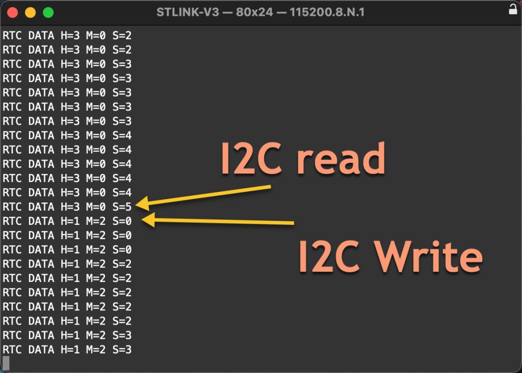
Note when second part becomes 5, new data for hours and minutes are written.
Happy coding 😉
Add Comment