In this guide of STM32H5, we shall take a look at the UART and how to configure the UART of STM32H563 Nucleo board to transmit data.
In this guide, we shall cover the following:
- What is UART.
- Driver development.
- Results.
1. What is UART:
To transfer data, computers adopt two method: serial and parallel. In serial communication data is sent a bit at a time (1 line)while in parallel communication 8 or more lines are often used to transfer data. The UART is a form of serial communication. When distance is short, digital signal can be transferred as it is on a single wire and require no modulation. This is how PC keyboard transfer data between the keyboard and motherboard. For long distances like telephone lines, serial data communication requires a modem to modulate.We will not go into the details of this in this lesson, this shall be left for subsequent lessons.
Synchronous vs. Asynchronous
Serial communication operate in two ways : synchronous and asynchronous. In the synchronous mode, a block of data is sent at a time while in the asynchronous mode, a single byte of data is sent at a time. It is possible to write code to provide both the synchronous and asynchronous serial communication functions however this could turn out tedious and over complicated therefore, special chips are manufactured to perform these functions. When these chips are added to a microcontroller, they become known as Serial Communication Interface (SCI). The chip that provides the the asynchronous communication (UART) is the main theme of this lesson. The chip for synchronous communication is known as the USART and shall left for another lesson.
Asynchronous Communication Data Framing
The data is received in zeros and ones format, in order to make sense of the data, the sender and the receiver must agree on a set of rules i.e. a protocol, on how data is packed, how many bits constitute a character and when data begins and ends.
The Protocol
- Start and Stop bits
Asynchronous serial communication is widely used in character transfer. Each character is packed between start and stop bits. This is known as the framing.
start bit : Always 1 bit, value is always 0
stop bit: 1 or 2 bits, value is always 1
Lets take an example. Lets say we are transferring ASCII character ‘A’
its binary code is 0100 0001 and 0x41 in hex.Furthermore, it is framed between a start bit and 2 stop bits. This is what its frame will look like.
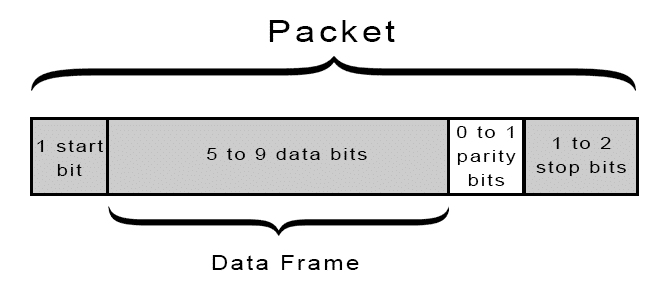
2. Parity bit
Some systems require parity bit in order to maintain data integrity.The parity bit of a character byte is included in the data frame after the stop bit(s).
3.Rate of data transfer : Baud rate/bps
We shall explain this concept with an example. Lets say we are asked to calculate the number of bits used and time taken in transferring 50 pages of text, each with 80×25 characters. Assuming 8 bits per character and 1 stop bit
solution
For each character a total of 10 bits is used ( 1 start bit, 8 bits character, 1 stop bit).
Therefore total number of bits = 80 x 25 x10 = 20,000 bits per page
50 pages implies, 50×20,000 = 1,000,000 bits.
Therefore it will take 1 million bits to transfer this information.
The time it takes to transfer the entire data using
a. 9600 baudrate implies, 1,000,000 / 9600 = 204 seconds
b. 57,600 baudrate implies 1,000,000 /57,600 = 17 seconds
Baudrate simply means the transfer of bits per second. There are various standardized baudrate we can choose from when we program our serial communication devices. The key thing is, both communication devices must have the same baudrate. We shall see this later on in our example code.
2. Driver Development:
Create new project with name of UART, for how to create new project, please refer to this guide here.
Before we continue, we need to find which pins of the STM32H563 is connected to the VCP (Virtual COM Port) of the embedded ST-Link V3.
In order to find this, we need to check the user manual of STM32H5 Nucleo-144 (UM3115).
From the hardware layout section, we can find:
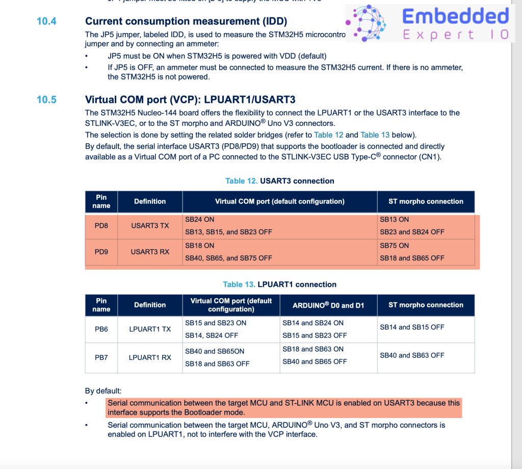
Hence, PD8 and PD9 is connected to the UARTS of the STM32H563 Nucleo-144.
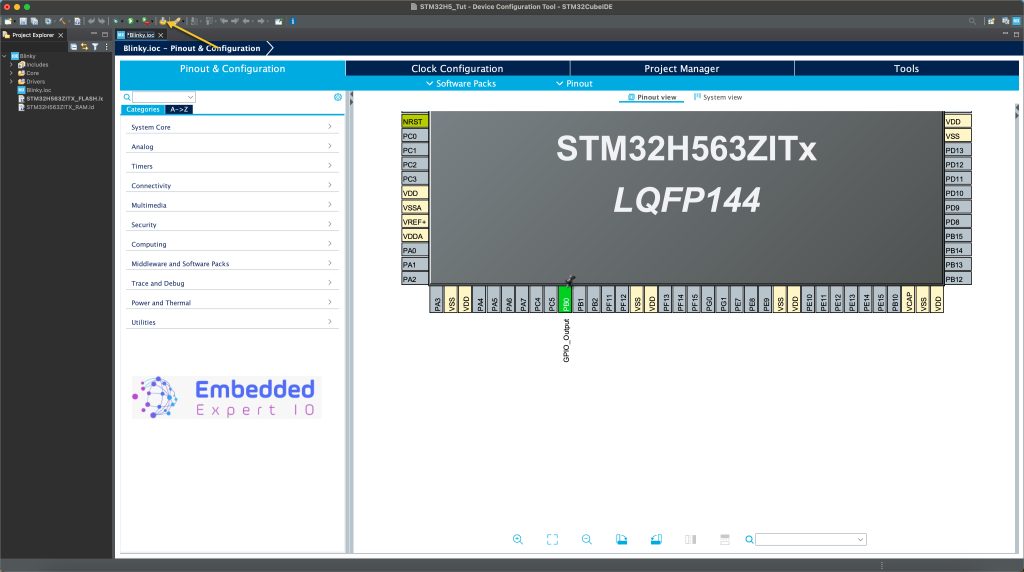
Once the project is created, from the CubeMX section:
Configure PD8 and PD9 for UART as following:
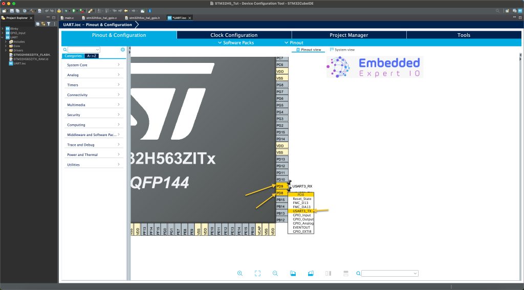
Next, from Connectivity, select UART3 and enable it as following:
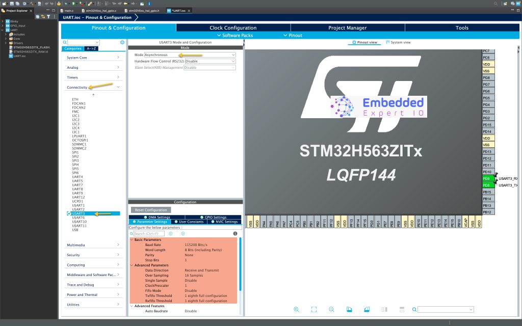
Keep the configuration as is since at this point, we don’t need to modify it as this point.
Next click on generate code as following:
This will save the project and generate the code.
This will open the main.c file.
Next, in user begin include section of the main.c file, include the stdio library as following:
#include "stdio.h"
Next, we shall retarget the printf to use the UART as following:
In user code begin 0:
int __io_putchar(int ch)
{
	HAL_UART_Transmit(&huart3, &ch, 1, 10);
	return ch;
}
This function will redirect the data of the pirntf from the buffer to the UART.
The HAL_UART_Transmit takes the following parameters:
- HandleTypedef to the UART which is UART3 in this case.
- Point to the character array which is ch in this case taken from the function call.
- Length of the data which is 1 since we are transmitting byte by byte.
- Time out which is 10ms for each character.
Thats all for the pinrtf retarget.
In user code begin 3 in the while 1 loop:
	  printf("Hello from EmbeddedExpertIO\r\n");
	  HAL_Delay(500);
Print the text and delay by 500ms.
That all for the guide.
Save the project, build it and run it on your STM32H563Zi board.

3. Results:
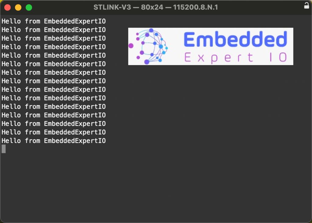
Open your serial terminal program and set the baudrate to 115200 and you should get the following:
Happy coding 😉
Add Comment