In this guide, we shall see how to use micropython to read analog signal applied to analog pin of STM32F411 Nucleo-64.
In this guide, we shall cover the following:
- What is ADC.
- Firmware Development.
- Results.
1. What is ADC:
In electronics, an analog-to-digital converter (ADC, A/D, or A-to-D) is a system that converts an analog signal, such as a sound picked up by a microphone or light entering a digital camera, into a digital signal that can be read by STM32.
ADCs can vary greatly between microcontroller. The ADC on the STM32F411 is a 12-bit ADC meaning it has the ability to detect 4096(2^12) discrete analog levels (which is also called Resolution). Some microcontrollers have 8-bit ADCs (2^8 = 256 discrete levels) and some have 16-bit ADCs (2^16 = 65,536 discrete levels).
The way an ADC works is fairly complex. There are a few different ways to achieve this feat (see Wikipedia for a list), but one of the most common technique uses the analog voltage to charge up an internal capacitor and then measure the time it takes to discharge across an internal resistor. The microcontroller monitors the number of clock cycles that pass before the capacitor is discharged. This number of cycles is the number that is returned once the ADC is complete. Other methods used called Successive-approximation ADC which you can read about it in details from this wikipedia page (Link)
For more information about how the adc of STM32F4 works, refer to the user manual (RM0383).
1.2 Relating ADC Value to Voltage
The ADC reports a ratio metric value. This means that the ADC assumes 3.3V is 4095 and anything less than 3.3V will be a ratio between 3.3V and 4095.
For example if the sensor has output voltage of 1.66V hence the ADC output will be (4095/3.3)*1.66=2059.
2. Firmware Development:
Before we start the firmware development, we need to install and configure thonny. For more details, please refer to this guide here.
After the configuration, we can develop the firmware.
We start by importing machine as following:
import machine
Also, include the time for delays as following:
import time
Since the MCU has multiple ADC pins which they are fixed to STM32F411RE, we can declare the adc as following:
adc1 = machine.ADC(0)  # ADC_CH0 ADC input
adc2 = machine.ADC(1)  # ADC_CH1 ADC input
By default, the ADC is initialized in polling mode, single conversion.
Declare while loop as following:
while True:
    value = adc1.read_u16()
    value = value >> 4  # Scale down to 12 bits (0 to 4095)
    voltage = value * (3.3 / 4095)  # Convert to volts
    print("ADC1 Value:", value, "Voltage:", voltage, "V")

    value = adc2.read_u16()
    value = value >> 4  # Scale down to 12 bits (0 to 4095)
    voltage = value * (3.3 / 4095)  # Convert to volts
    print("ADC2 Value:", value, "Voltage:", voltage, "V")
    time.sleep(1)  # Read every 1 second
In the while, we shall read the ADC pin individually by using read_u16.
Since the function map the value to 16-bit, we need to convert it back to 12 by using the following:
value = value>>4
This will convert the value back to correct 12-bit.
Hence, the full code as following:
import machine
import time

adc1 = machine.ADC(0)  # ADC_CH0 ADC input
adc2 = machine.ADC(1)  # ADC_CH1 ADC input


while True:
    value = adc1.read_u16()
    value = value >> 4  # Scale down to 12 bits (0 to 4095)
    voltage = value * (3.3 / 4095)  # Convert to volts
    print("ADC1 Value:", value, "Voltage:", voltage, "V")

    value = adc2.read_u16()
    value = value >> 4  # Scale down to 12 bits (0 to 4095)
    voltage = value * (3.3 / 4095)  # Convert to volts
    print("ADC2 Value:", value, "Voltage:", voltage, "V")
    time.sleep(1)  # Read every 1 second
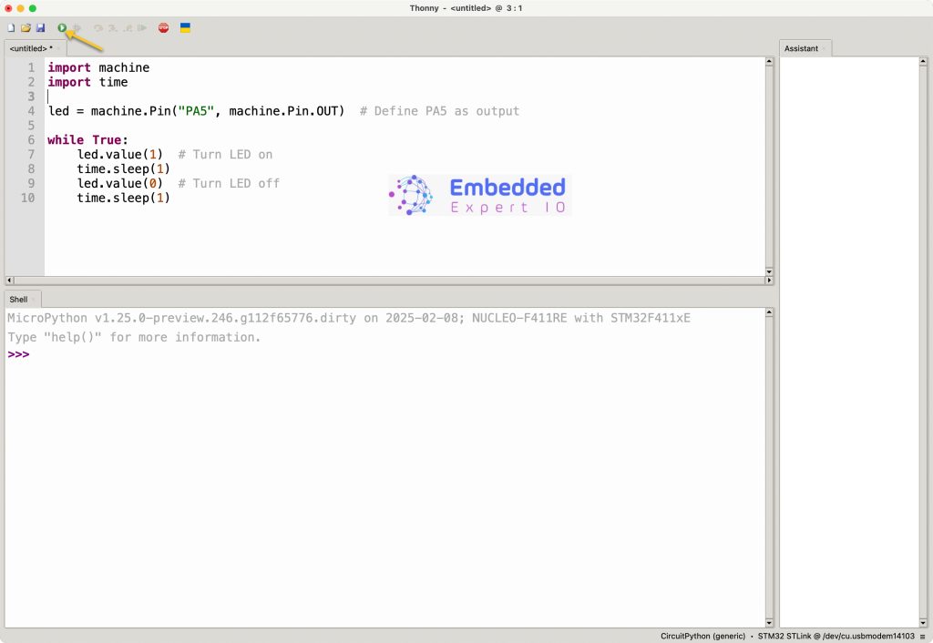
Click on run as following:
3. Results:
In the shell, you should see the results as following:

Happy coding 😉
Add Comment