In this guide, we shall see what is rotary encoder and how to use timer of the STM32H5 to read the pulses using hardware which will relief the MCU from processing the pulses of the encoder.
In this guide, we shall cover the following:
- What is encoder.
- Connection.
- Driver development.
- Results.
1. What is Encoder:
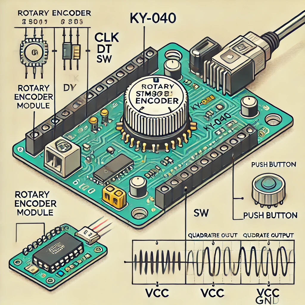
A rotary encoder, also called a shaft encoder, is an electro-mechanical device that converts the angular position or motion of a shaft or axle to analog or digital output signals.
Rotary encoders are used in a wide range of applications that require monitoring or control, or both, of mechanical systems, including industrial controls, robotics, photographic lenses, computer input devices such as optomechanical mice and trackballs, controlled stress rheometers, and rotating radar platforms.
1.2 Encoder types:
- Mechanical: Also known as conductive encoders. A series of circumferential copper tracks etched onto a PCB is used to encode the information via contact brushes sensing the conductive areas. Mechanical encoders areeconomical but susceptible to mechanical wear. They are common in human interfaces such as digital multimeters
- Optical: This uses a light shining onto a photodiode through slits in a metal or glass disc. Reflective versions also exist. This is one of the most common technologies. Optical encoders are very sensitive to dust.
- On-Axis Magnetic: This technology typically uses a specially magnetized 2 pole neodymium magnet attached to the motor shaft. Because it can be fixed to the end of the shaft, it can work with motors that only have 1 shaft extending out of the motor body. The accuracy can vary from a few degrees to under 1 degree. Resolutions can be as low as 1 degree or as high as 0.09 degree (4000 CPR, Count per Revolution). Poorly designed internal interpolation can cause output jitter, but this can be overcome with internal sample averaging.
- Off-Axis Magnetic: This technology typically employs the use of rubber bonded ferrite magnets attached to a metal hub. This offers flexibility in design and low cost for custom applications. Due to the flexibility in many off axis encoder chips they can be programmed to accept any number of pole widths so the chip can be placed in any position required for the application. Magnetic encoders operate in harsh environments where optical encoders would fail to work. (from wikipedia)
1.3 Encoder Output:
In out case, the encoder shall generate pulses on both DT and CLK lines in a certain manner that can be read by the timer of stm32. In the figure below, is the output from shaft encoder when rotating clockwise. Clk is yellow and DT is Blue.
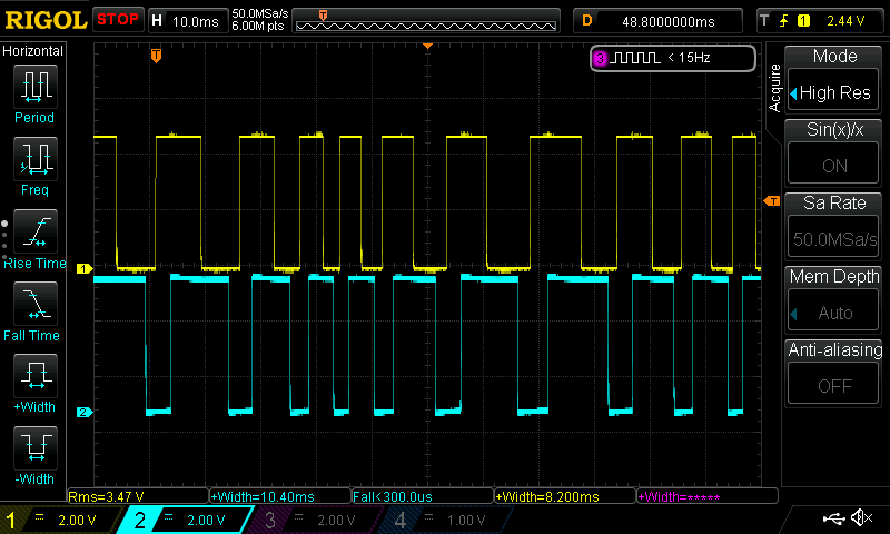
When the shaft encoder rotate clockwise, CLK like pulled high first then DT line which indicates there is rotation.
When the counter clock rotation occurs, the DT line is pulled high first then the CLK line.

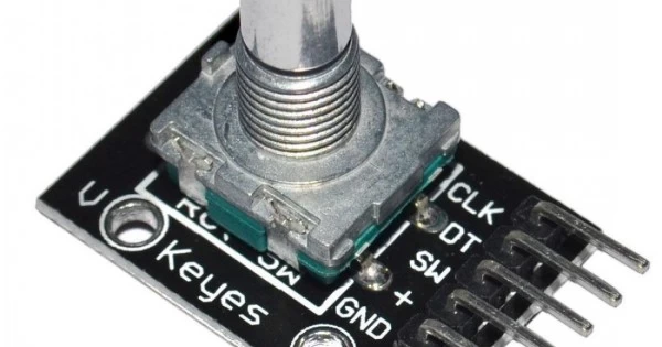
2. Connection:
The connection as following:
The module is shown below:
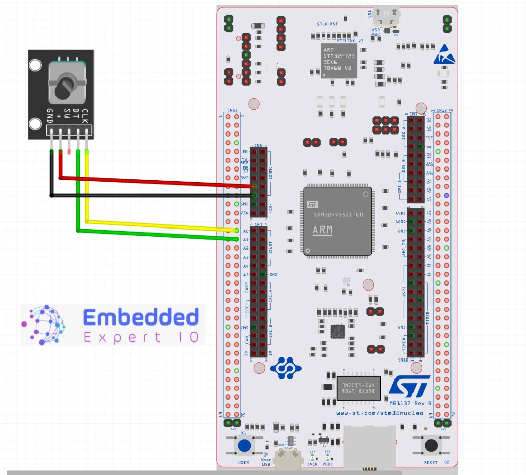
The connection is as following
| Encoder Pin | STM32H563Zi Nucleo-144 |
| GND | GND |
| + | 5V |
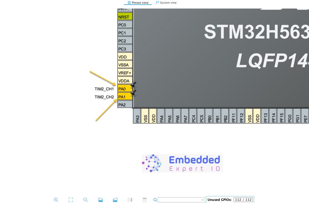
| DT | PA1 |
| CLK | PA0 |
3. Driver Development:
We start off by creating new project with name of timer_encoder. For how to create a new project, please refer to this guide here.
Next, set PA0 and PA1 for TIM2_CH1 and TIM2_CH2 respectively as following:
Next, from timers, select TIM2 and set Combine Channels to be encoder mode as following:
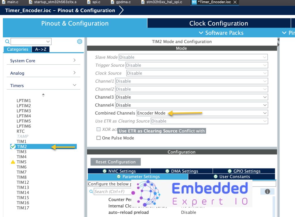
Next, configure the timer as following:
- Set the counter value to be the counter pulses for each rotation multiplied by 4 and minus 1 (In this case 20*4 which is 80-1 79).
- Encoder Mode Encoder Mode TI1 and TI2.
The rest shall be left as default.
Save the project and this will generate the code.
Once the project has been generated, the main.c file will be opened.
In main.c, in user code begin PV, declare the following:
uint32_t encoder_value;
This will hold the reading of the encoder pulses.
Next, in user code begin 2 in main function, start the timer in encoder mode as following:
HAL_TIM_Encoder_Start(&htim2, TIM_CHANNEL_ALL);
The function HAL_TIM_Encoder_Start takes two parameters as following:
- Handletypedef of the timer which is htim2 in this case.
- Channel number, we shall use all the timer channels since the timer is no longer operation in any other mode.
In user code begin 3, we shall read the timer counter as following:
encoder_value=__HAL_TIM_GET_COUNTER(&htim2);
Thats all.
Build the project and start a debugging session as following:

4. Results:
Add encoder_value to the live expressions and rotate the encoder. The value shall change with the rotation. (Mine has minor issues and doesn’t work properly).

Happy coding 😉
Add Comment