The ST7920-based 128×64 GLCD is a versatile graphical display commonly used in embedded systems for visualizing text and graphics. When interfaced with an STM32F4 using SPI, it enables efficient communication while minimizing pin usage. This guide covers the setup, wiring, and SPI communication necessary to integrate the display with STM32F4. The first part of your guide will cover the introduction, hardware connection, and STM32CubeMX setup.
In this guide. we shall cover the following:
- Introduction to GLCD.
- Gathering the required documents.
- Connection.
- STM32CubeIDE Setup.
1. Introduction to GLCD:
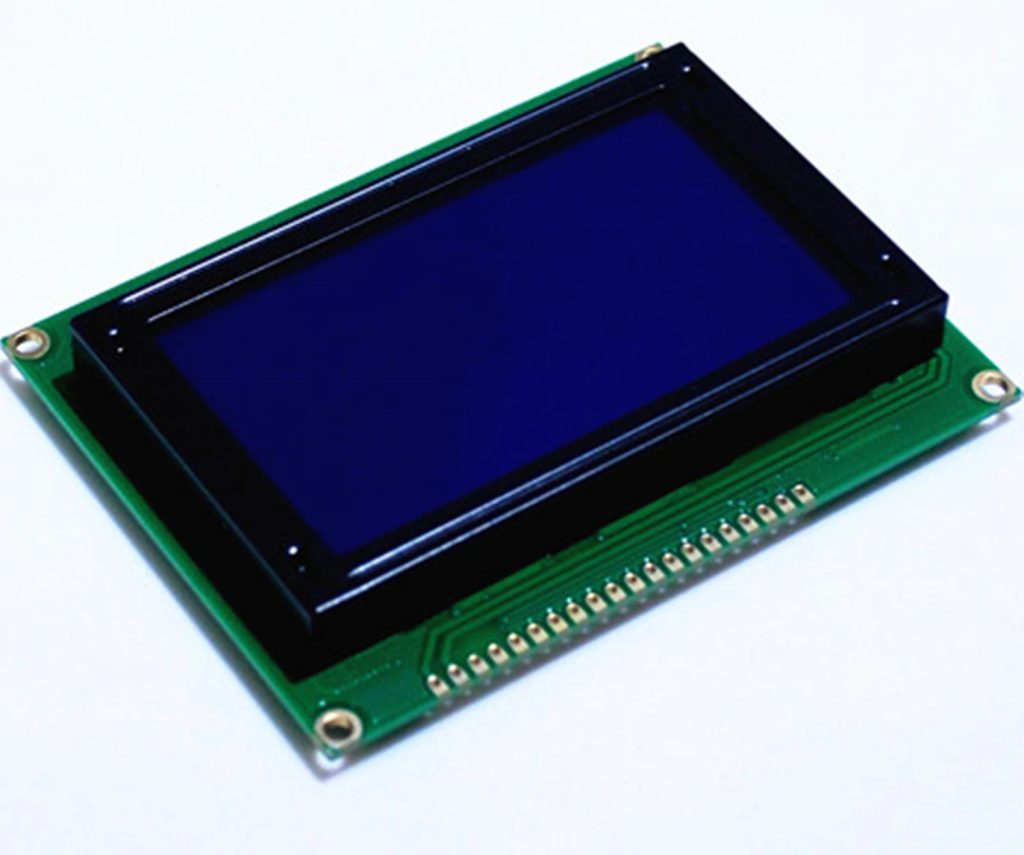
At first glance, the 128×64 Graphical LCD Module seems like a bigger brother to the famous 16×2 LCD or 20×4 LCD Modules, with their similar construction and almost similar pin layout.
But there is a significant difference between those two. 16×2 or 20×4 LCDs are essentially character displays. They can only display alpha-numeric characters and some simple custom characters that are confined to a 5×8 matrix.
Coming to the 128×64 Graphical LCD, as the name suggests, it is a Graphical Display consisting of 128×64 i.e., 8192 individually controllable dots.
By using different combinations of pixels, we can basically display characters of various sizes. But the magic doesn’t end there. You can display images and graphics (small animations) as well. In a 128×64 LCD Module, there are 64 rows and 128 columns.
ST7920 LCD Controller
There are several versions of the Graphical LCD in the market. Even though the usage, application and implementations are almost identical, the main difference lies in the internal LCD Controller used to drive the dot matrix display.
Some of the commonly used LCD Controllers are KS0108, SSD1306, ST7920, SH1106, SSD1322, etc. The pin out of the final LCD Module might vary depending on the LCD Controller used. So, please verify the LCD Controller as well as the pin out before making a purchase.
The Graphical LCD Module I purchased consists of ST7920 Controller. It is manufactured by Sitronix and supports three types of bus interfaces i.e., 8-bit mode, 4-bit mode and Serial interface.
If you have used 16×2 LCD Display earlier, then you might be familiar with both 4-bit as well as 8-bit parallel interfaces. The serial interface is something new and we will explore this option in this project.
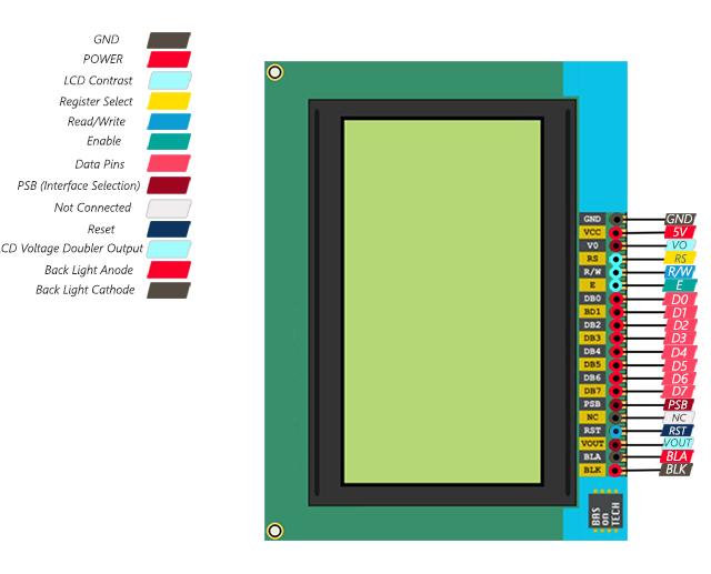
128×64 LCD Pinout
As I already mentioned, double-check with the manufacturer about the pinout of the Graphical LCD Module. The following table describes the pinout of the 128×64 LCD Module that I have.
| Pin Number | Pin Name | Pin Description |
| 1 | GND | Ground |
| 2 | VCC | Supply Voltage |
| 3 | VO | Contrast Adjust |
| 4 | RS | Register Select (CS in Serial) |
| 5 | RW | Read / Write Control (Serial Data In) |
| 6 | E | Enable (Serial CLK) |
| 7 – 14 | D0 – D7 | Data |
| 15 | PSB | Interface Selection (0: Serial, 1: 8-bit/4-bit Parallel) |
| 16 | NC | Not Connected |
| 17 | RST | Reset |
| 18 | VOUT | LCD Voltage Doubler Output |
| 19 | BLA | Backlight LED Anode |
| 20 | BLK | Backlight LED Cathode |
2. Gathering the Required Documents:
The following documents are needed:
ST7920 datasheet from here.
STM32F411 Nucleo-64 User manual from here.
That all for the required documents.
3. Connection:
Since STM32F411 Nucleo-64 has Arduino Pins, we can use it as identifier for SPI pins.
The pins as following:
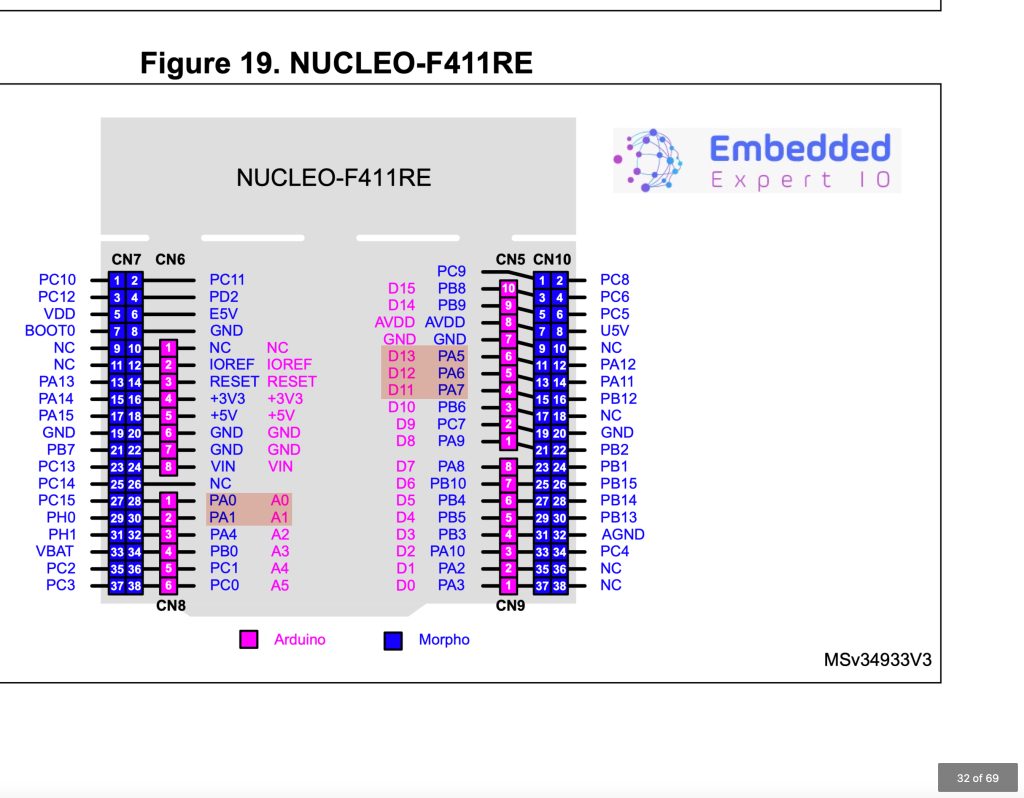
The needed pins are PA5, PA6 and PA7 which are for the SPI.
We shall use PA0 and PA1 for RS (Register Select) and RST (Reset) respectively.
Hence, the connection as following:
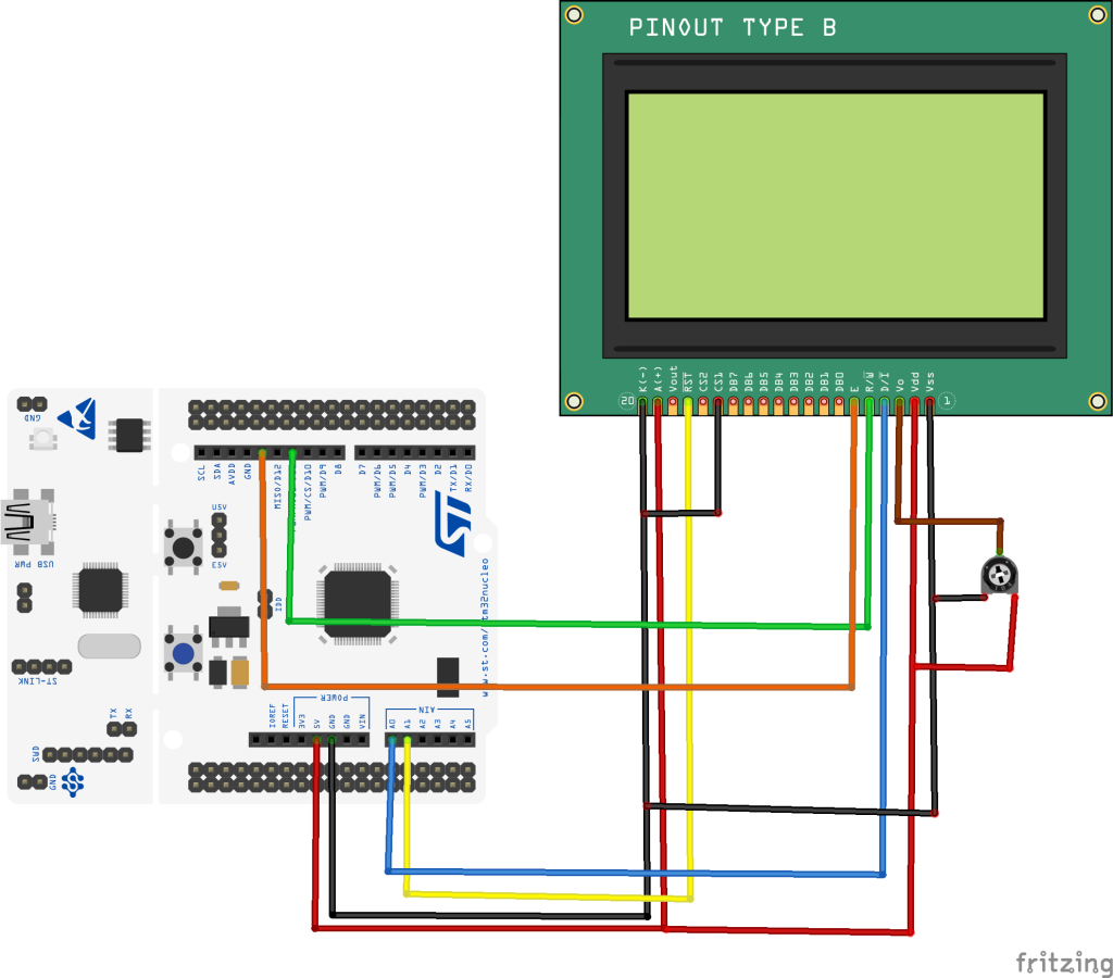
| STM32F411 Nucleo-64 | GLCD12864 |
| 5V | Vdd and LED+ (A) |
| GND | Vss, LED- (K) and PSB |
| PA0 | RS |
| PA1 | RST |
| PA7 (MOSI) | RW |
| PA5 (SCK) | En |
4. STM32CubeIDE Setup:
Open STM32CubeIDE after selecting the workspace and create new project as following:

Select the MCU:

Give the project a name:
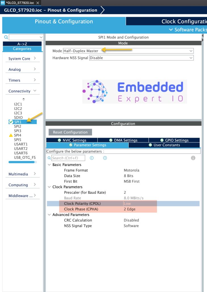
Once the STM32CubeMX window is open, from connectivity, select SPI1 and enable it in half duplex master as following:
Configure the SPI as following:
- Set prescaler to achieve 8Mb/s of baudrate.
- Set CPOL to low.
- Set CPHA to 2 Edge.
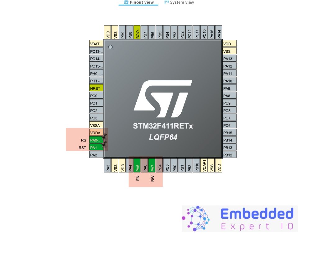
Next, enable PA0 and PA1 as output give them as following including the SPI1 pins as following:
From Project Manager tab, select Code Generation and enable Generate peripheral initialization as pair of .c/.h files per peripheral as following:
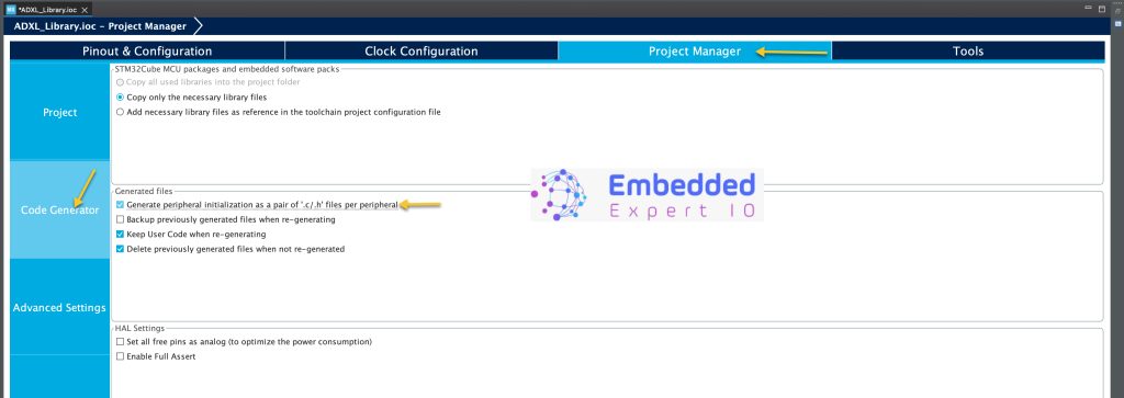
Save the project and this will generate the code.
Stay tuned for part2.
Happy coding 😉
2 Comments
thank you for sharing.
I like to make a thermal dispersion flow switch. it has two NTC and a resistor for heating.
if have a project that use NTC, it can help me .
NTC is a resistor after all.
Use voltage divider to measure the voltage using adc and calibrate it according to the temperature range needed.
Add Comment