In this guide on STM32H5, we shall configure the UART to transmit data using DMA to offload the transmission process to the DMA rather than sending it byte by byte.
In this guide, we shall cover the following:
- STM32CubeMX Configuration.
- Firmware Development.
- Results.
1.STM32CubeMX Configuration:
We start off by creating new project with name of UART_DMA. For how to create a project using STM32CubeIDE for STM32H5, please refer to this guide here.
After the project creation, configure the UART as following:
From the hardware layout section, we can find:
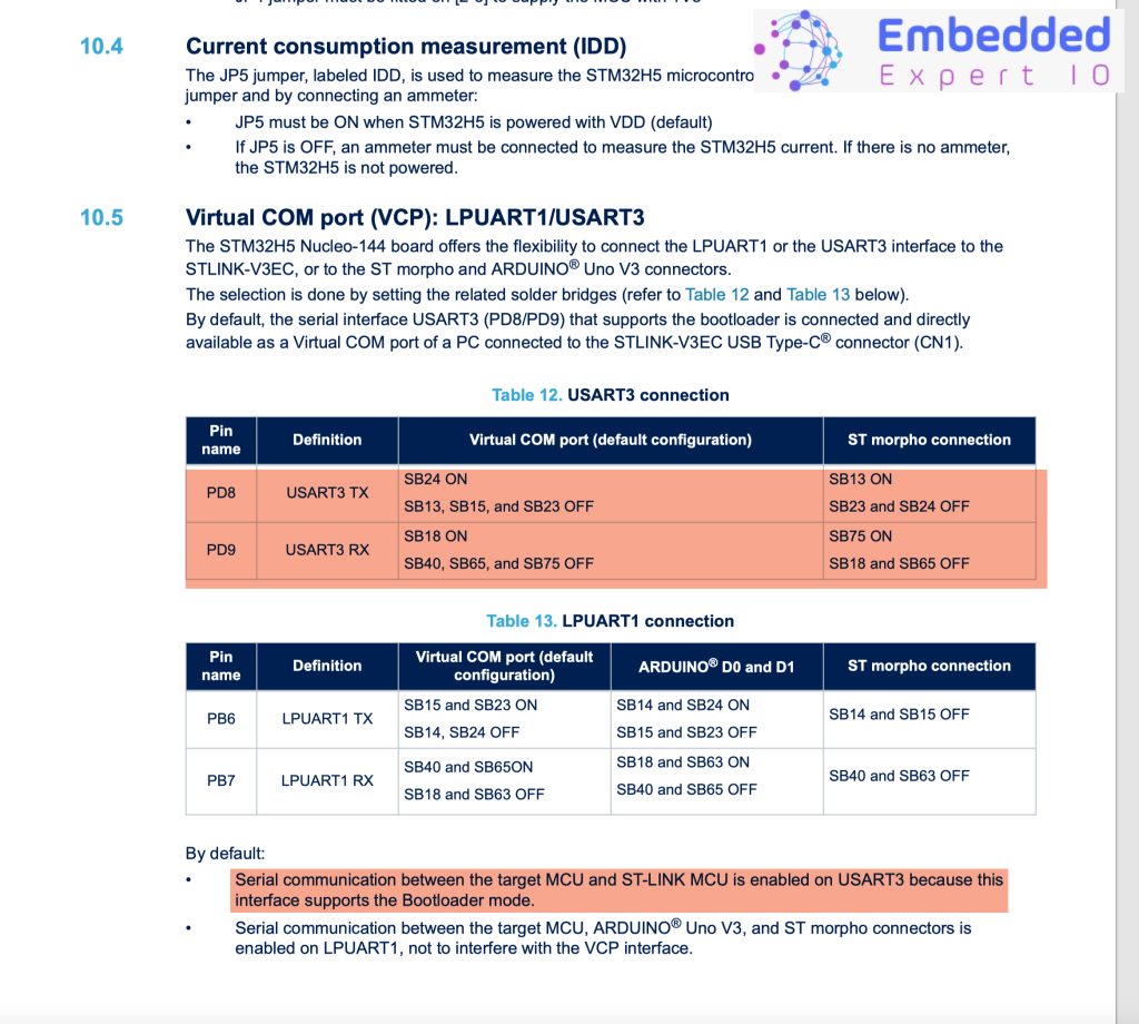
Hence, PD8 and PD9 is connected to the UARTS of the STM32H563 Nucleo-144.
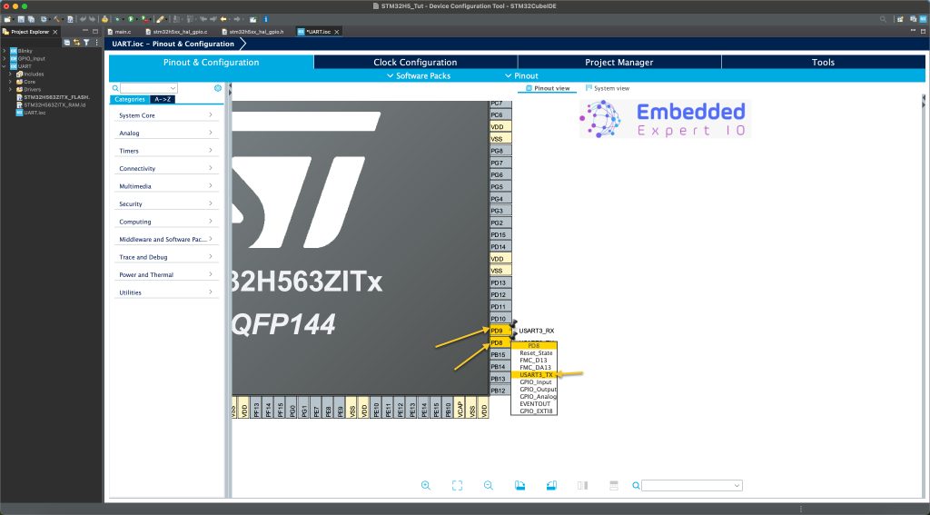
Once the project is created, from the CubeMX section:
Configure PD8 and PD9 for UART as following:
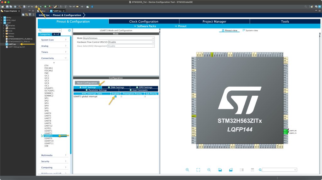
Next, from Connectivity, select UART3 and enable it as following:
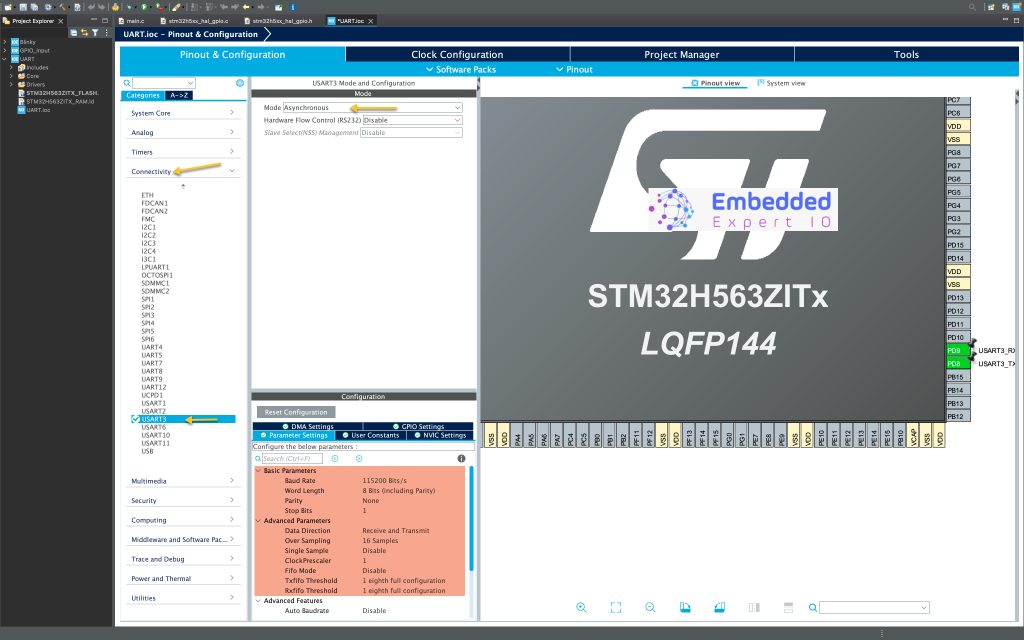
Keep the configuration as is since at this point, we don’t need to modify it as this point.
Next, we shall enable the interrupt as following:
Next, from connectivity, select UART3, then NVIC tab and enable UART3 global interrupt as following:
Next, from system core GPDMA1, enable Channel0 in standard request mode as following:
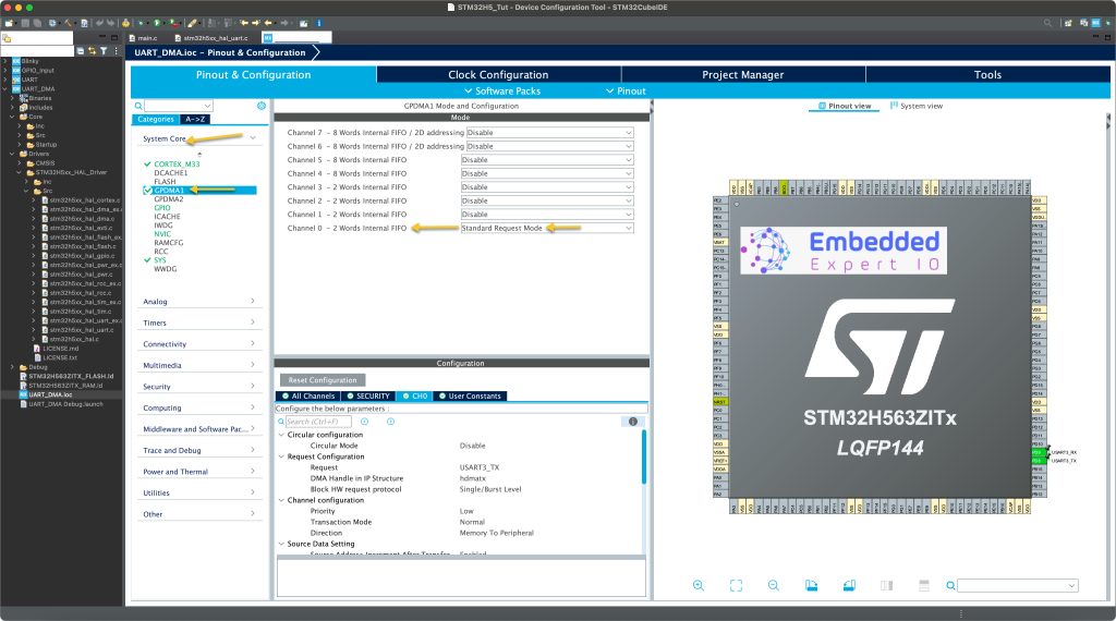
Next, we shall configure the channel.
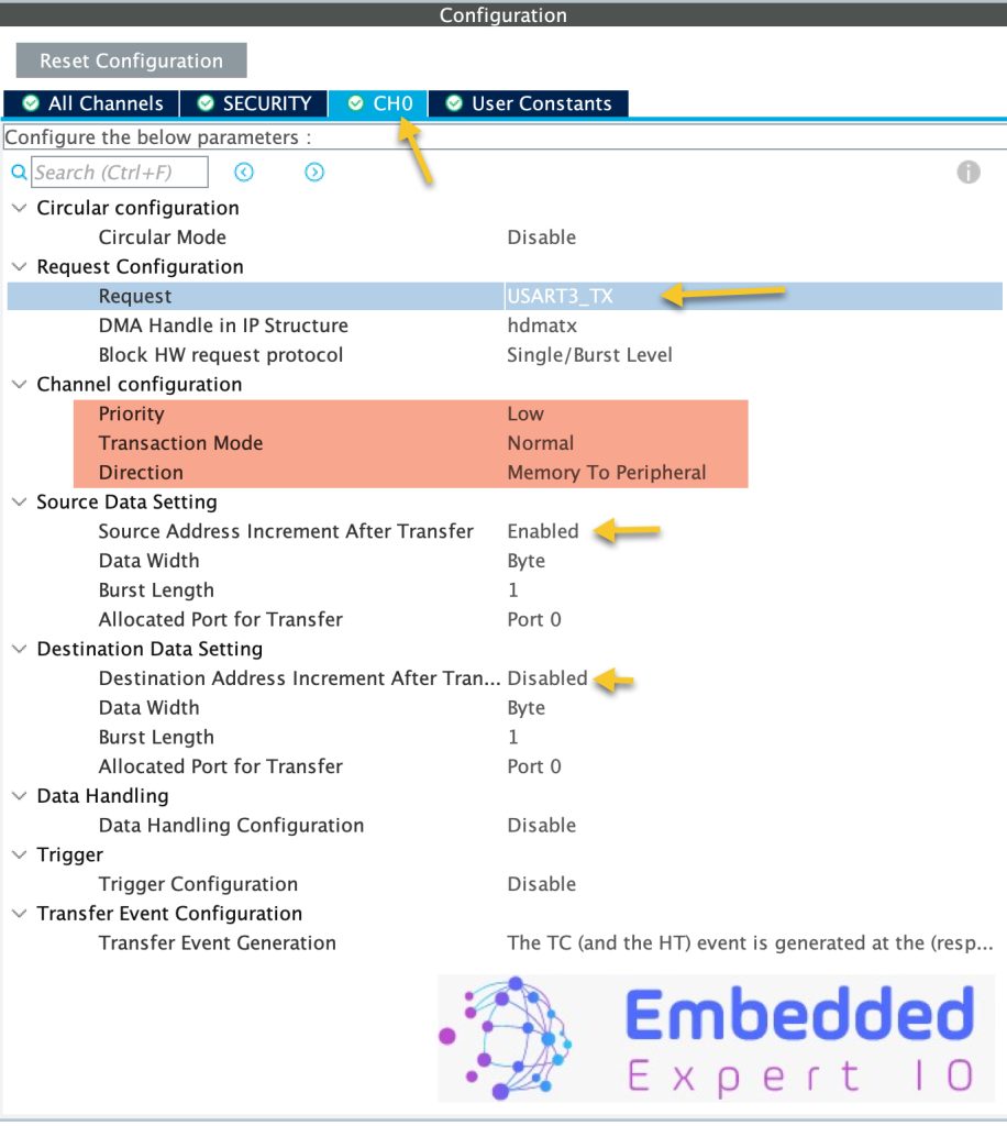
Open the CH0 tab and configure it as following:
- Circular mode to disabled.
- Request, select USART3_TX.
- Priority to low.
- Transaction mode to normal.
- Direction to Memory to Peripheral.
For the source data settings:
- Enable the address increment after each transfer.
- Data width to byte.
- Burst length to 1.
- Port to Port 0.
For the destination settings:
- Disable address increment after each transaction.
- The rest of the settings similar to the source data setting.
Click on generate to generate the code.
Thats all for the configuration.
2. Firmware Development:
In main.c file, in user code begin includes, include the following header files:
#include "stdint.h"
#include "stdio.h"
In user code begin PV, declare the following three variables as following:
uint8_t TxBuffer[100];


uint16_t Counter=0;

volatile uint8_t done;
The TxBuffer shall hold the characters to be send over UART in DMA mode.
Counter is a variable shall be incremented after each transfer.
done is set when UART finished the sending operation and ready to transmit the next set of data.
In user code begin 0, include the following function:
void HAL_UART_TxCpltCallback(UART_HandleTypeDef *huart)
{
	done=1;
}
This function is defined as weak function in stm32h5xx_hal_uart.c source file.
This function shall be called when the UART has completed the transfer all the data in either, interrupt mode or DMA mode.
It can handle multiple UART as the same time, just ensure that you are getting the data correctly as following for example:
void HAL_UART_TxCpltCallback(UART_HandleTypeDef *huart)
{
	if(huart->Instance==USART3)
	{
		done=1;
	}
}
In user code begin in while 1 loop:
	  uint16_t len=sprintf(TxBuffer,"Counter Value is =%d\r\n",Counter++);
	  HAL_UART_Transmit_DMA(&huart3, TxBuffer, len);
	  while(done==0);
	  done=0;
	  HAL_Delay(10);
sprintf will always return the number of the characters has been written, we shall store this in the variable called len.
Start the transmit using DMA using the DMA:
HAL_UART_Transmit_DMA(&huart3, TxBuffer, len);
It takes the following parameters:
- Instant to the UART to be used which is uart3 in this case.
- Buffer to hold the data to be transmitted.
- Length of the buffer.
Wait until done is set to 1, then reset it back to zero and wait for 10ms.
Thats all for the firmware.
Save the project, build it and run it on your STM32H563Zi board.

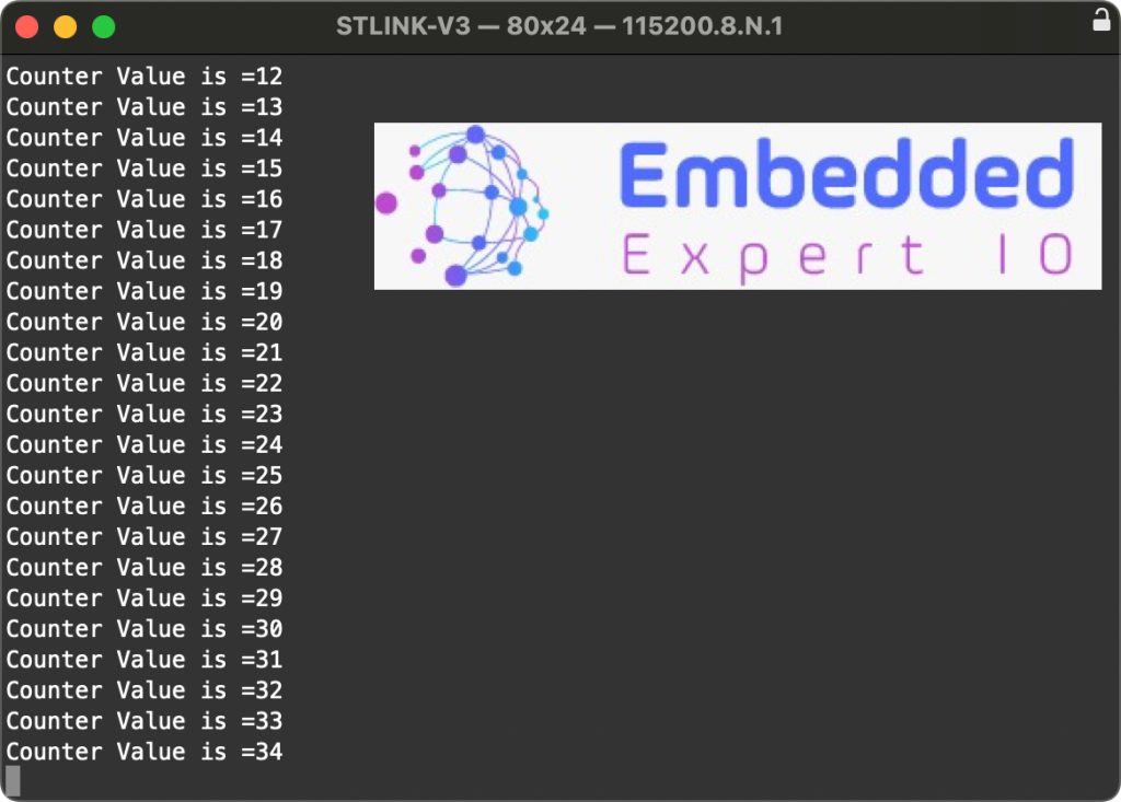
3. Results:
Open your favourite serial terminal program, set the baudrate to 115200 and you should get this with incremented values.
Happy coding 😉
Add Comment