In this guide on STM32G070, we shall cover I2S peripheral and take a look what is I2S and I2S feature in STM32G070.
In this guide, we shall cover the following:
- What is I2S.
- Feature of I2S of STM32G070.
- Driver Development.
- Results.
1. What is I2S:
I²S (Inter-IC Sound), pronounced “eye-squared-ess,” is an electrical serial bus interface standard used for connecting digital audio devices together. It facilitates the communication of PCM (pulse-code modulated) audio data between integrated circuits within an electronic device. Here are some key details about I²S:
- Bus Configuration:
- The I²S bus consists of at least three lines:
- Bit Clock (BCLK): Also known as the “continuous serial clock,” this line synchronizes the data transmission. It pulses once for each discrete bit of data on the data lines.
- Word Clock (WS): Indicates whether channel 1 (WS = 0) or channel 2 (WS = 1) is being transmitted. I²S allows two channels to be sent on the same data line.
- Multiplexed Data Line (SD): Carries the actual audio data. It can be called by various names such as SDATA, SDIN, SDOUT, DACDAT, or ADCDAT.
- Optionally, there may be a Master Clock(typically 256 times the LRCLK) for synchronizing analog/digital converters.
- The I²S bus consists of at least three lines:
- Timing and Synchronization:
- The word select clock (WS) has a 50% duty cycle and the same frequency as the sample rate. For stereo material, left audio is transmitted during the low cycle of WS, and the right channel during the high cycle.
- Data is latched on the rising edge of the serial clock (SCK).
- History:
- Introduced by Philips Semiconductor (now NXP Semiconductors) in 1986.
- Last revised in February 2022, updating terms from “master” and “slave” to “controller” and “target”.
I²S is commonly used in audio codecs, microcontrollers, digital signal processors, and other sound-processing devices. It provides high-quality audio transmission, precise synchronization, and efficient data transfer, making it a preferred choice for digital audio communication.
2. Feature Of I2S in STM32G070:
Half-duplex communication (only transmitter or receiver)
• Master or slave operations
• 8-bit programmable linear prescaler to reach accurate audio sample frequencies (from 8 kHz to 192 kHz)
• Data format may be 16-bit, 24-bit or 32-bit
• Packet frame is fixed to 16-bit (16-bit data frame) or 32-bit (16-bit, 24-bit, 32-bit data frame) by audio channel
• Programmable clock polarity (steady state)
• Underrun flag in slave transmission mode, overrun flag in reception mode (master and slave) and Frame Error Flag in reception and transmitter mode (slave only)
• 16-bit register for transmission and reception with one data register for both channel sides
• Supported I 2 S protocols:
– I 2 S Philips standard
– MSB-justified standard (left-justified)
– LSB-justified standard (right-justified)
– PCM standard (with short and long frame synchronization on 16-bit channel frame or 16-bit data frame extended to 32-bit channel frame)
• Data direction is always MSB first
• DMA capability for transmission and reception (16-bit wide)
• Master clock can be output to drive an external audio component. Ratio is fixed at 256 × F S (where F S is the audio sampling frequency)
Block diagram of I2S in STM32G070:

3. Driver Development:
We start of by creating new project with name of I2S. For how to create new project, please refer to this guide.
From multimedia, select I2S, the enable half duplex master as following:
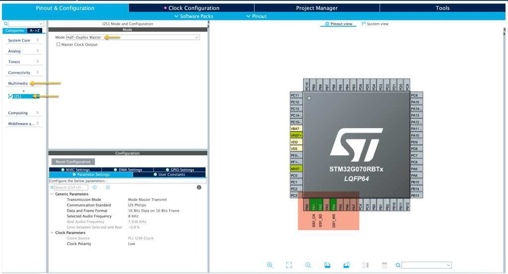
Since there is no I2S enabled device connected, no need to enable Master Clock Output.
This will automatically enable the following pins:
- PA1 as I2S Clock.
- PA2 as I2S Data.
- PA4 as Word Select (left right channel).
Leave the settings as default.
Then from Clock Configuration, Set /P to 4 so it will provide 32MHz. This is necessary for I2S.
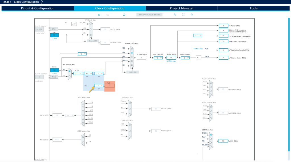
Thats all for the configuration.
Save the project. This shall generate the code.
In User Code Begin PV, declare the following array:
uint16_t i2s_data[10]=
{
0,1,2,3,4,5,6,7,8,9
};
In User Code Begin 3 in while loop:
	  HAL_I2S_Transmit(&hi2s1, i2s_data, 10,100);
	  HAL_Delay(10);
The HAL_I2S_Transmit takes the following parameters:
- handleTypedef for i2s, which is hi2s1 in this case.
- pointer to the data to be transmitted, i2s_data in this case.
- Size of data, in this case 10.
- Last one is timeout.
Save the project build the project and run it:

4. Results:
Connect logic analyzer to the pin and set the decoding mode to i2s and you should get this:

Happy coding 😉
Add Comment