
In the previous guide (here), we were able to transmit data over I2S using DMA, in this guide, we shall initialize the CS43L22 which is stereo DAC.
In this guide, we shall cover the following:
- Enabling circular mode for DMA.
- Header file development.
- Source file development.
- Main code.
- Source code download.
- Results.
18. Enabling Circular Mode for DMA:
In I2S source file, the I2S3_Init function:
In the DMA configuration add the following to the configuration:
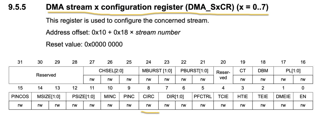
DMA_SxCR_CIRC
Hence the configuration as following:
	/*Configure DMA with the following parameters
	 * 1.Channel is 0.
	 * Memory increment mode.
	 * Direction Memory to Peripheral.
	 * Enable Transfer Complete Interrupt.
	 * Enable Circular Mode
	 *
	 * */
	DMA1_Stream7->CR|=(0x00<<DMA_SxCR_CHSEL_Pos)|DMA_SxCR_MINC|DMA_SxCR_DIR_0|DMA_SxCR_TCIE|DMA_SxCR_CIRC;
That all for the DMA section.
19. Header File Development:
Create new header file with name of CS43L22.h
Within the header file:
Include the header guard as following:
#ifndef CS43L22_H_
#define CS43L22_H_


#endif /* CS43L22_H_ */
Within the header file:
Include stdint library as following:
#include "stdint.h"
Declare the following define statements for the CS43L22 registers:
#define POWER_CONTROL1				0x02
#define POWER_CONTROL2				0x04
#define CLOCKING_CONTROL 	  		0x05
#define INTERFACE_CONTROL1			0x06
#define INTERFACE_CONTROL2			0x07
#define PASSTHROUGH_A				0x08
#define PASSTHROUGH_B				0x09
#define MISCELLANEOUS_CONTRLS		0x0E
#define PLAYBACK_CONTROL			0x0F
#define PASSTHROUGH_VOLUME_A		0x14
#define PASSTHROUGH_VOLUME_B		0x15
#define PCM_VOLUME_A				0x1A
#define PCM_VOLUME_B				0x1B
#define CONFIG_00					0x00
#define CONFIG_47					0x47
#define CONFIG_32					0x32
Registers of the volume control:
#define CS43L22_REG_MASTER_A_VOL    0x20
#define CS43L22_REG_MASTER_B_VOL    0x21
Device address:
#define DAC_I2C_ADDR (0x94>>1)
Note: The address shifted to right by 1 since the i2c driver will shift the address to left 1.
Macro for mute:
#define CS43_MUTE 0x00
Channel selection:
#define CS43_RIGHT					0x01
#define CS43_LEFT				 	0x02
#define CS43_RIGHT_LEFT	 			0x03
Convert volume:
#define VOLUME_CONVERT_A(Volume)    (((Volume) > 100)? 255:((uint8_t)(((Volume) * 255) / 100)))
#define VOLUME_CONVERT_D(Volume)    (((Volume) > 100)? 24:((uint8_t)((((Volume) * 48) / 100) - 24)))
Type of inputs either I2S or analog:
typedef enum
{
	MODE_I2S = 0,
	MODE_ANALOG,
}CS43_MODE;
Declare the following functions:
void CS43_Init(CS43_MODE outputMode);
void CS43_Enable_RightLeft(uint8_t side);
void CS43_SetVolume(uint8_t volume);
void CS43_Start(void);
void CS43_Stop(void);
void CS43L22_Pin_RST_Init(void);
void CS43L22_RST_Pin_Low(void);
void CS43L22_RST_Pin_High(void);
Hence the entire header file as following:
#ifndef CS43L22_H_
#define CS43L22_H_

#include "stdint.h"

#define POWER_CONTROL1				0x02
#define POWER_CONTROL2				0x04
#define CLOCKING_CONTROL 	  		0x05
#define INTERFACE_CONTROL1			0x06
#define INTERFACE_CONTROL2			0x07
#define PASSTHROUGH_A				0x08
#define PASSTHROUGH_B				0x09
#define MISCELLANEOUS_CONTRLS		0x0E
#define PLAYBACK_CONTROL			0x0F
#define PASSTHROUGH_VOLUME_A		0x14
#define PASSTHROUGH_VOLUME_B		0x15
#define PCM_VOLUME_A				0x1A
#define PCM_VOLUME_B				0x1B
#define CONFIG_00					0x00
#define CONFIG_47					0x47
#define CONFIG_32					0x32

#define CS43L22_REG_MASTER_A_VOL    0x20
#define CS43L22_REG_MASTER_B_VOL    0x21

#define DAC_I2C_ADDR 				(0x94>>1)

#define CS43_MUTE				 	0x00

#define CS43_RIGHT					0x01
#define CS43_LEFT				 	0x02
#define CS43_RIGHT_LEFT	 			0x03

#define VOLUME_CONVERT_A(Volume)    (((Volume) > 100)? 255:((uint8_t)(((Volume) * 255) / 100)))
#define VOLUME_CONVERT_D(Volume)    (((Volume) > 100)? 24:((uint8_t)((((Volume) * 48) / 100) - 24)))


typedef enum
{
	MODE_I2S = 0,
	MODE_ANALOG,
}CS43_MODE;


//------------ Public functions ------------//
void CS43_Init(CS43_MODE outputMode);
void CS43_Enable_RightLeft(uint8_t side);
void CS43_SetVolume(uint8_t volume);
void CS43_Start(void);
void CS43_Stop(void);
void CS43L22_Pin_RST_Init(void);
void CS43L22_RST_Pin_Low(void);
void CS43L22_RST_Pin_High(void);

#endif /* CS43L22_H_ */
20. Source File Development:
Create new source file with name of CS43L22.c.
Within the source file:
Include the i2c and and CS43L22 header files:
#include "i2c.h"
#include "CS43L22.h"
Declare an array that hold some variables:
static uint8_t iData[2];
Since we need to read/write from/to chip, we need to declare the following two functions:
// Function(1): Write to register
static void write_register(uint8_t reg, uint8_t *data)
{
	iData[0] = reg;
	iData[1] = data[0];
	i2c_writeByte(DAC_I2C_ADDR, (char)iData[0], (char)iData[1]);

}
// Function(2): Read from register
static void read_register(uint8_t reg, uint8_t *data)
{
	char tempData=0;
	i2c_readByte(DAC_I2C_ADDR,(char)reg, &tempData);
	*data=tempData;
}
First one is to write to certain register and the second one is for reading from a register.
Since the chip features hardware reset which is connected to PD4 as shown in the schematic:
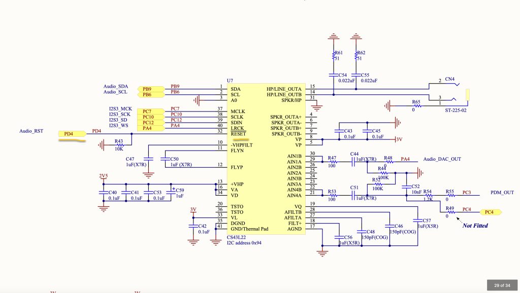
For the pin initialization:
void CS43L22_Pin_RST_Init(void)
{
	RCC->AHB1ENR|=RCC_AHB1ENR_GPIODEN;

	GPIOD->MODER|=GPIO_MODER_MODE4_0;
	GPIOD->MODER&=~GPIO_MODER_MODE4_1;
}
For setting the pin either high or low:
void CS43L22_RST_Pin_Low(void)
{
	GPIOD->BSRR=GPIO_BSRR_BR4;
}

void CS43L22_RST_Pin_High(void)
{
	GPIOD->BSRR=GPIO_BSRR_BS4;
}
Setting the pin low will reset the chip and high will release the chip from reset state.
For the initialization of CS42L22:
void CS43_Init(CS43_MODE outputMode)
{

	CS43L22_RST_Pin_High();

	//(2): Power down
	iData[1] = 0x01;
	write_register(POWER_CONTROL1,iData);

	//(3): Enable Right and Left headphones
	iData[1] =  (2 << 6);  // PDN_HPB[0:1]  = 10 (HP-B always onCon)
	iData[1] |= (2 << 4);  // PDN_HPA[0:1]  = 10 (HP-A always on)
	iData[1] |= (3 << 2);  // PDN_SPKB[0:1] = 11 (Speaker B always off)
	iData[1] |= (3 << 0);  // PDN_SPKA[0:1] = 11 (Speaker A always off)
	write_register(POWER_CONTROL2,&iData[1]);

	//(4): Automatic clock detection
	iData[1] = (1 << 7);
	write_register(CLOCKING_CONTROL,&iData[1]);

	//(5): Interface control 1
	read_register(INTERFACE_CONTROL1, iData);
	iData[1] &= (1 << 5); // Clear all bits except bit 5 which is reserved
	iData[1] &= ~(1 << 7);  // Slave
	iData[1] &= ~(1 << 6);  // Clock polarity: Not inverted
	iData[1] &= ~(1 << 4);  // No DSP mode
	iData[1] &= ~(1 << 2);  // Left justified, up to 24 bit (default)
	iData[1] |= (1 << 2);
	iData[1] |=  (3 << 0);  // 16-bit audio word length for I2S interface
	write_register(INTERFACE_CONTROL1,&iData[1]);


	//(6): Passthrough A settings
	read_register(PASSTHROUGH_A, &iData[1]);
	iData[1] &= 0xF0;      // Bits [4-7] are reserved
	iData[1] |=  (1 << 0); // Use AIN1A as source for passthrough
	write_register(PASSTHROUGH_A,&iData[1]);


	//(7): Passthrough B settings
	read_register(PASSTHROUGH_B, &iData[1]);
	iData[1] &= 0xF0;      // Bits [4-7] are reserved
	iData[1] |=  (1 << 0); // Use AIN1B as source for passthrough
	write_register(PASSTHROUGH_B,&iData[1]);


	//(8): Miscellaneous register settings
	read_register(MISCELLANEOUS_CONTRLS, &iData[1]);
	if(outputMode == MODE_ANALOG)
	{
		iData[1] |=  (1 << 7);   // Enable passthrough for AIN-A
		iData[1] |=  (1 << 6);   // Enable passthrough for AIN-B
		iData[1] &= ~(1 << 5);   // Unmute passthrough on AIN-A
		iData[1] &= ~(1 << 4);   // Unmute passthrough on AIN-B
		iData[1] &= ~(1 << 3);   // Changed settings take affect immediately
	}
	else if(outputMode == MODE_I2S)
	{
		iData[1] = 0x02;
	}
	write_register(MISCELLANEOUS_CONTRLS,&iData[1]);
	//(9): Unmute headphone and speaker

	read_register(PLAYBACK_CONTROL, &iData[1]);
	iData[1] = 0x00;
	write_register(PLAYBACK_CONTROL,&iData[1]);

	//(10): Set volume to default (0dB)
	iData[1] = 0x00;
	write_register(PASSTHROUGH_VOLUME_A,&iData[1]);
	write_register(PASSTHROUGH_VOLUME_B,&iData[1]);
	write_register(PCM_VOLUME_A,&iData[1]);
	write_register(PCM_VOLUME_B,&iData[1]);
}
For selecting left, right or both channels:
// Function(2): Enable Right and Left headphones
void CS43_Enable_RightLeft(uint8_t side)
{
	switch (side)
	{
		case 0:
			iData[1] =  (3 << 6);  // PDN_HPB[0:1]  = 10 (HP-B always onCon)
			iData[1] |= (3 << 4);  // PDN_HPA[0:1]  = 10 (HP-A always on)
			break;
		case 1:
			iData[1] =  (2 << 6);  // PDN_HPB[0:1]  = 10 (HP-B always onCon)
			iData[1] |= (3 << 4);  // PDN_HPA[0:1]  = 10 (HP-A always on)
			break;
		case 2:
			iData[1] =  (3 << 6);  // PDN_HPB[0:1]  = 10 (HP-B always onCon)
			iData[1] |= (2 << 4);  // PDN_HPA[0:1]  = 10 (HP-A always on)
			break;
		case 3:
			iData[1] =  (2 << 6);  // PDN_HPB[0:1]  = 10 (HP-B always onCon)
			iData[1] |= (2 << 4);  // PDN_HPA[0:1]  = 10 (HP-A always on)
			break;
		default:
			break;
	}
	iData[1] |= (3 << 2);  // PDN_SPKB[0:1] = 11 (Speaker B always off)
	iData[1] |= (3 << 0);  // PDN_SPKA[0:1] = 11 (Speaker A always off)
	write_register(POWER_CONTROL2,&iData[1]);
}
For Setting the volume:
// Function(3): Set Volume Level
void CS43_SetVolume(uint8_t volume)
{
	int8_t tempVol = volume - 50;
	tempVol = tempVol*(127/50);
	uint8_t myVolume =  (uint8_t )tempVol;
	iData[1] = myVolume;
	write_register(PASSTHROUGH_VOLUME_A,&iData[1]);
	write_register(PASSTHROUGH_VOLUME_B,&iData[1]);

	iData[1] = VOLUME_CONVERT_D(volume);

	/* Set the Master volume */
	write_register(CS43L22_REG_MASTER_A_VOL,&iData[1]);
	write_register(CS43L22_REG_MASTER_B_VOL,&iData[1]);
}
Start the DAC functionality:
// Function(4): Start the Audio DAC
void CS43_Start(void)
{
	// Write 0x99 to register 0x00.
	iData[1] = 0x99;
	write_register(CONFIG_00,&iData[1]);
	// Write 0x80 to register 0x47.
	iData[1] = 0x80;
	write_register(CONFIG_47,&iData[1]);
	// Write '1'b to bit 7 in register 0x32.
	read_register(CONFIG_32, &iData[1]);
	iData[1] |= 0x80;
	write_register(CONFIG_32,&iData[1]);
	// Write '0'b to bit 7 in register 0x32.
	read_register(CONFIG_32, &iData[1]);
	iData[1] &= ~(0x80);
	write_register(CONFIG_32,&iData[1]);
	// Write 0x00 to register 0x00.
	iData[1] = 0x00;
	write_register(CONFIG_00,&iData[1]);
	//Set the "Power Ctl 1" register (0x02) to 0x9E
	iData[1] = 0x9E;
	write_register(POWER_CONTROL1,&iData[1]);
}
For stoping the DAC:
void CS43_Stop(void)
{
	iData[1] = 0x01;
	write_register(POWER_CONTROL1,&iData[1]);
}
Hence, the source code as following:
#include "i2c.h"
#include "CS43L22.h"


static uint8_t iData[2];


//(1): Functions definitions
//-------------- Static Functions ---------------//
// Function(1): Write to register
static void write_register(uint8_t reg, uint8_t *data)
{
	iData[0] = reg;
	iData[1] = data[0];
	i2c_writeByte(DAC_I2C_ADDR, (char)iData[0], (char)iData[1]);

}
// Function(2): Read from register
static void read_register(uint8_t reg, uint8_t *data)
{
	char tempData=0;
	i2c_readByte(DAC_I2C_ADDR,(char)reg, &tempData);
	*data=tempData;
}


void CS43L22_Pin_RST_Init(void)
{
	RCC->AHB1ENR|=RCC_AHB1ENR_GPIODEN;

	GPIOD->MODER|=GPIO_MODER_MODE4_0;
	GPIOD->MODER&=~GPIO_MODER_MODE4_1;
}

void CS43L22_RST_Pin_Low(void)
{
	GPIOD->BSRR=GPIO_BSRR_BR4;
}

void CS43L22_RST_Pin_High(void)
{
	GPIOD->BSRR=GPIO_BSRR_BS4;
}


//-------------- Public Functions ----------------//
// Function(1): Initialisation

void CS43_Init(CS43_MODE outputMode)
{

	CS43L22_RST_Pin_High();

	//(2): Power down
	iData[1] = 0x01;
	write_register(POWER_CONTROL1,iData);

	//(3): Enable Right and Left headphones
	iData[1] =  (2 << 6);  // PDN_HPB[0:1]  = 10 (HP-B always onCon)
	iData[1] |= (2 << 4);  // PDN_HPA[0:1]  = 10 (HP-A always on)
	iData[1] |= (3 << 2);  // PDN_SPKB[0:1] = 11 (Speaker B always off)
	iData[1] |= (3 << 0);  // PDN_SPKA[0:1] = 11 (Speaker A always off)
	write_register(POWER_CONTROL2,&iData[1]);

	//(4): Automatic clock detection
	iData[1] = (1 << 7);
	write_register(CLOCKING_CONTROL,&iData[1]);

	//(5): Interface control 1
	read_register(INTERFACE_CONTROL1, iData);
	iData[1] &= (1 << 5); // Clear all bits except bit 5 which is reserved
	iData[1] &= ~(1 << 7);  // Slave
	iData[1] &= ~(1 << 6);  // Clock polarity: Not inverted
	iData[1] &= ~(1 << 4);  // No DSP mode
	iData[1] &= ~(1 << 2);  // Left justified, up to 24 bit (default)
	iData[1] |= (1 << 2);
	iData[1] |=  (3 << 0);  // 16-bit audio word length for I2S interface
	write_register(INTERFACE_CONTROL1,&iData[1]);


	//(6): Passthrough A settings
	read_register(PASSTHROUGH_A, &iData[1]);
	iData[1] &= 0xF0;      // Bits [4-7] are reserved
	iData[1] |=  (1 << 0); // Use AIN1A as source for passthrough
	write_register(PASSTHROUGH_A,&iData[1]);


	//(7): Passthrough B settings
	read_register(PASSTHROUGH_B, &iData[1]);
	iData[1] &= 0xF0;      // Bits [4-7] are reserved
	iData[1] |=  (1 << 0); // Use AIN1B as source for passthrough
	write_register(PASSTHROUGH_B,&iData[1]);


	//(8): Miscellaneous register settings
	read_register(MISCELLANEOUS_CONTRLS, &iData[1]);
	if(outputMode == MODE_ANALOG)
	{
		iData[1] |=  (1 << 7);   // Enable passthrough for AIN-A
		iData[1] |=  (1 << 6);   // Enable passthrough for AIN-B
		iData[1] &= ~(1 << 5);   // Unmute passthrough on AIN-A
		iData[1] &= ~(1 << 4);   // Unmute passthrough on AIN-B
		iData[1] &= ~(1 << 3);   // Changed settings take affect immediately
	}
	else if(outputMode == MODE_I2S)
	{
		iData[1] = 0x02;
	}
	write_register(MISCELLANEOUS_CONTRLS,&iData[1]);
	//(9): Unmute headphone and speaker

	read_register(PLAYBACK_CONTROL, &iData[1]);
	iData[1] = 0x00;
	write_register(PLAYBACK_CONTROL,&iData[1]);

	//(10): Set volume to default (0dB)
	iData[1] = 0x00;
	write_register(PASSTHROUGH_VOLUME_A,&iData[1]);
	write_register(PASSTHROUGH_VOLUME_B,&iData[1]);
	write_register(PCM_VOLUME_A,&iData[1]);
	write_register(PCM_VOLUME_B,&iData[1]);
}

// Function(2): Enable Right and Left headphones
void CS43_Enable_RightLeft(uint8_t side)
{
	switch (side)
	{
		case 0:
			iData[1] =  (3 << 6);  // PDN_HPB[0:1]  = 10 (HP-B always onCon)
			iData[1] |= (3 << 4);  // PDN_HPA[0:1]  = 10 (HP-A always on)
			break;
		case 1:
			iData[1] =  (2 << 6);  // PDN_HPB[0:1]  = 10 (HP-B always onCon)
			iData[1] |= (3 << 4);  // PDN_HPA[0:1]  = 10 (HP-A always on)
			break;
		case 2:
			iData[1] =  (3 << 6);  // PDN_HPB[0:1]  = 10 (HP-B always onCon)
			iData[1] |= (2 << 4);  // PDN_HPA[0:1]  = 10 (HP-A always on)
			break;
		case 3:
			iData[1] =  (2 << 6);  // PDN_HPB[0:1]  = 10 (HP-B always onCon)
			iData[1] |= (2 << 4);  // PDN_HPA[0:1]  = 10 (HP-A always on)
			break;
		default:
			break;
	}
	iData[1] |= (3 << 2);  // PDN_SPKB[0:1] = 11 (Speaker B always off)
	iData[1] |= (3 << 0);  // PDN_SPKA[0:1] = 11 (Speaker A always off)
	write_register(POWER_CONTROL2,&iData[1]);
}

// Function(3): Set Volume Level
void CS43_SetVolume(uint8_t volume)
{
	int8_t tempVol = volume - 50;
	tempVol = tempVol*(127/50);
	uint8_t myVolume =  (uint8_t )tempVol;
	iData[1] = myVolume;
	write_register(PASSTHROUGH_VOLUME_A,&iData[1]);
	write_register(PASSTHROUGH_VOLUME_B,&iData[1]);

	iData[1] = VOLUME_CONVERT_D(volume);

	/* Set the Master volume */
	write_register(CS43L22_REG_MASTER_A_VOL,&iData[1]);
	write_register(CS43L22_REG_MASTER_B_VOL,&iData[1]);
}

// Function(4): Start the Audio DAC
void CS43_Start(void)
{
	// Write 0x99 to register 0x00.
	iData[1] = 0x99;
	write_register(CONFIG_00,&iData[1]);
	// Write 0x80 to register 0x47.
	iData[1] = 0x80;
	write_register(CONFIG_47,&iData[1]);
	// Write '1'b to bit 7 in register 0x32.
	read_register(CONFIG_32, &iData[1]);
	iData[1] |= 0x80;
	write_register(CONFIG_32,&iData[1]);
	// Write '0'b to bit 7 in register 0x32.
	read_register(CONFIG_32, &iData[1]);
	iData[1] &= ~(0x80);
	write_register(CONFIG_32,&iData[1]);
	// Write 0x00 to register 0x00.
	iData[1] = 0x00;
	write_register(CONFIG_00,&iData[1]);
	//Set the "Power Ctl 1" register (0x02) to 0x9E
	iData[1] = 0x9E;
	write_register(POWER_CONTROL1,&iData[1]);
}

void CS43_Stop(void)
{
	iData[1] = 0x01;
	write_register(POWER_CONTROL1,&iData[1]);
}
Please refer to the datasheet from here for more details about each register.
21. Main Code:
#include "delay.h"
#include "stdlib.h"
#include "i2s.h"
#include "CS43L22.h"
#include "i2c.h"
#include "stdio.h"
#include "math.h"


#define F_SAMPLE	96000.0f
#define F_OUT		2000.0f
#define PI 			3.14159f


uint16_t dataI2S[100];
float mySinVal;
float sample_dt;
uint16_t sample_N;
uint16_t i_t;


int main(void)
{
	delay_init(168000000);

	i2c_init();

	I2S3_Pins_Init();
	I2S3_Init();


	CS43L22_Pin_RST_Init();
	CS43_Init(MODE_I2S);
	CS43_SetVolume(100);
	CS43_Enable_RightLeft(CS43_RIGHT_LEFT);
	CS43_Start();

	sample_dt = F_OUT/F_SAMPLE;
	sample_N = F_SAMPLE/F_OUT;

	for(uint16_t i=0; i<sample_N; i++)
	{
		mySinVal = sinf(i*2*PI*sample_dt);

		dataI2S[i*2] = (mySinVal )*8000;    //Right data (0 2 4 6 8 10 12)

		dataI2S[i*2 + 1] =(mySinVal )*8000; //Left data  (1 3 5 7 9 11 13)
	}

	I2S_SendData_DMA(dataI2S, 100);

	while(1)
	{


	}


}
22. Source Code Download:
You may download the source code from here.
23. Results:
Since the main data shall generate sinewave with 2KHz, you should hear some loud noise from the headphone.
By probing on of the channels, you should get the following:

As you can see, we got 2KHz sinewave (almost due to approximation).
Happy coding 😉
Add Comment