
In the previous guide (here), we took a look what is I2S and how it works and it’s features. In this guide, we shall configure the I2S and send data using polling mode.
In this guide, we shall cover the following:
- I2S Clock Configuration.
- I2S Configuration.
- I2S Send data polling mode.
- Results.
8. I2S Clock Configuration:
Before we start configuration of the I2S, we need to enable the I2S clock in the RCC (Reset and Clock Control).
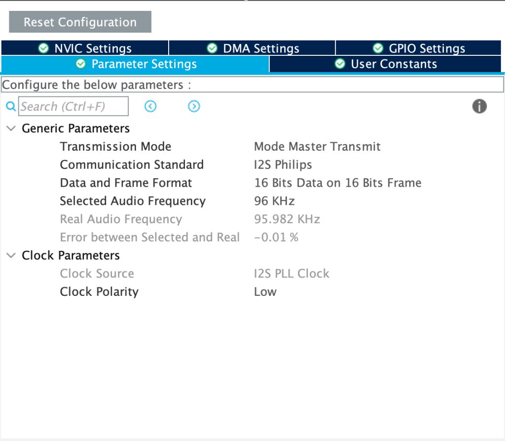
From the CubeMX, we can find that using PLLI2S N value of 172 and R of 2, we can achieve accurate 96KHz frequency for the audio:
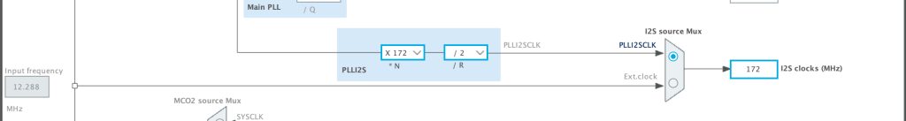
Hence, we can configure the clock as following:
Within sys_init source file, at the end of void SystemInit(void) function:
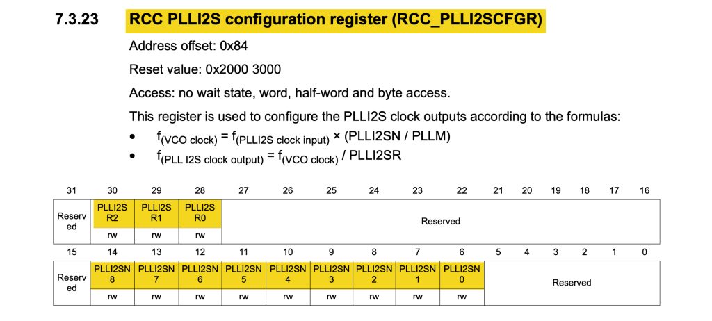
  /*I2S clock configuration*/
  RCC->PLLI2SCFGR=(0xAC<<RCC_PLLI2SCFGR_PLLI2SN_Pos)|(2<<RCC_PLLI2SCFGR_PLLI2SR_Pos);
Enable I2S clock:
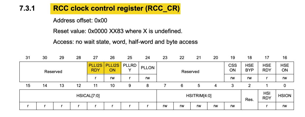
  RCC->CR|=RCC_CR_PLLI2SON;

  /*Wait until the clock is enabled*/

  while(!(RCC->CR & RCC_CR_PLLI2SRDY));
Thats all for the i2s clock configuration.
9. I2S Configuration:
Create new source and header file with name of i2s.c and i2s.h respectively.
Within the header file:
Include the header guard:
#ifndef I2S_H_
#define I2S_H_


#endif /* I2S_H_ */
Within the header guard:
Include stdint library:
#include "stdint.h"
Declare the following functions:
void I2S3_Pins_Init(void);
void I2S3_Init(void);
void I2S_SendData(uint16_t *data, uint16_t len);
Thats all for the header file.
Within the source file:
Include the following header file:
#include "i2s.h"
#include "stm32f4xx.h"
From the schematic of STM32F407-discovery board:
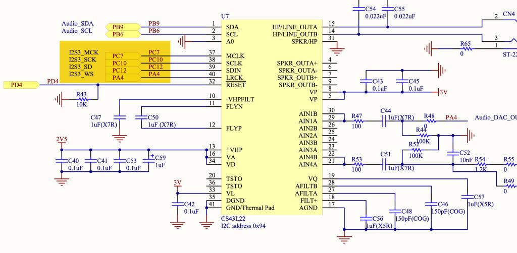
We can find the following:
- PC7 as master clock output.
- PC10 as Serial clock.
- PC12 as Serial Data.
- PA4 as Word Select (channel select left or right).
Note also that they all connected to I2S3 which is SPI3 (since I2S and SPI share same hardware).
Hence, for the pin initialization function:
void I2S3_Pins_Init(void)
{
	#define I2S_AF 0x06

	RCC->AHB1ENR|=RCC_AHB1ENR_GPIOCEN|RCC_AHB1ENR_GPIOAEN;

	GPIOA->MODER|=GPIO_MODER_MODE4_1;
	GPIOA->MODER&=~GPIO_MODER_MODE4_0;

	GPIOA->AFR[0]|=(I2S_AF<<GPIO_AFRL_AFSEL4_Pos);

	GPIOC->MODER|=GPIO_MODER_MODE7_1|GPIO_MODER_MODE10_1|GPIO_MODER_MODE12_1;

	GPIOC->MODER&=~(GPIO_MODER_MODE7_0|GPIO_MODER_MODE10_0|GPIO_MODER_MODE12_0);

	GPIOC->AFR[0]|=(I2S_AF<<GPIO_AFRL_AFSEL7_Pos);

	GPIOC->AFR[1]|=(I2S_AF<<GPIO_AFRH_AFSEL10_Pos)|(I2S_AF<<GPIO_AFRH_AFSEL12_Pos);


}
Note also the alternate function is the same for SPI3.
For the i2s intialization sequence:
First, we need to enable clock access to SPI3 as following:
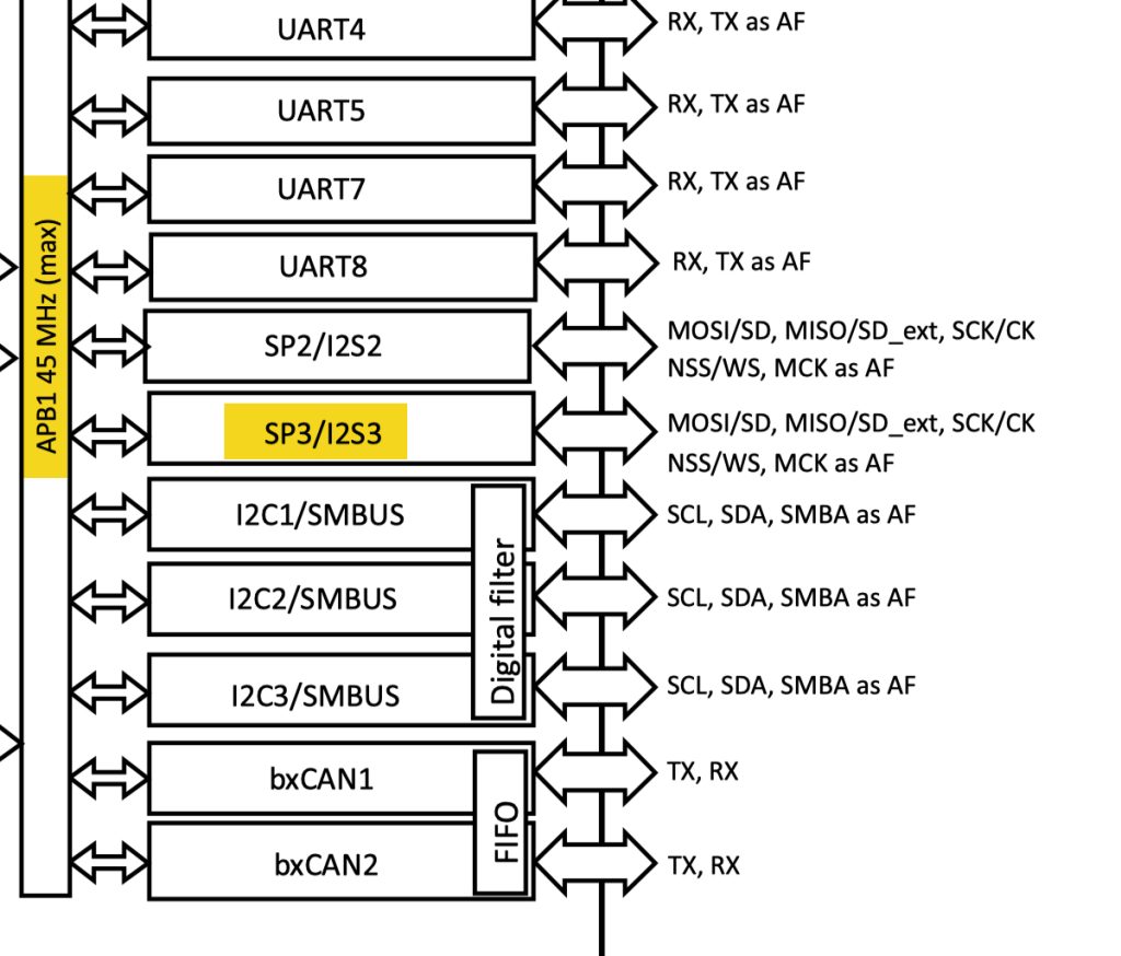
Since SPI3 is connected to APB1, we can enable it as following:
void I2S3_Init(void)
{
	/*Enable clock access to SPI3/I2S3*/

	RCC->APB1ENR|=RCC_APB1ENR_SPI3EN;
Set the mode to be I2S as following:
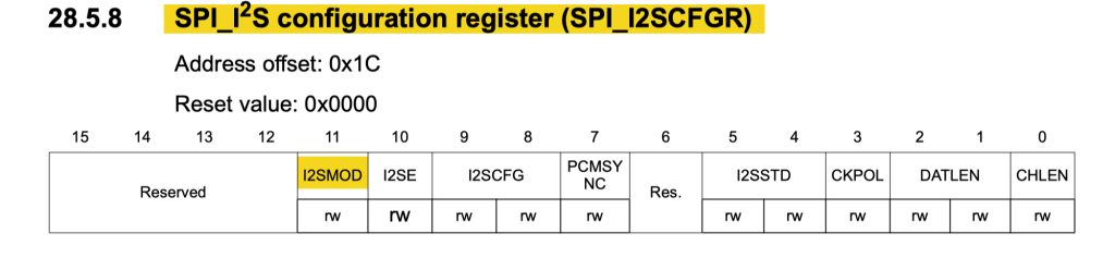
	/*Set SPI into I2S Mode*/
	SPI3->I2SCFGR|=SPI_I2SCFGR_I2SMOD;
Set the mode to master transmit:
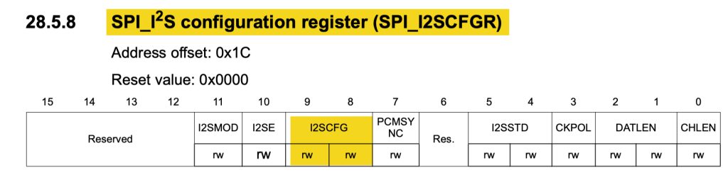
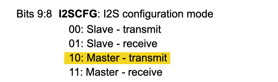
	/*Set the mode to master transmit*/
	SPI3->I2SCFGR|=SPI_I2SCFGR_I2SCFG_1;
Set the prescaler and odd value:
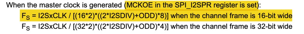
Since we are generating the master clock and the data is 16-bit.
By using I2SxCLK of 172Mhz, and FS of 96KHz we can I2SDIV as following:
- I2SDIV of 4 when ODD is 0.
- I2SDIV of 3 when ODD is 1.
Either one will work just fine.
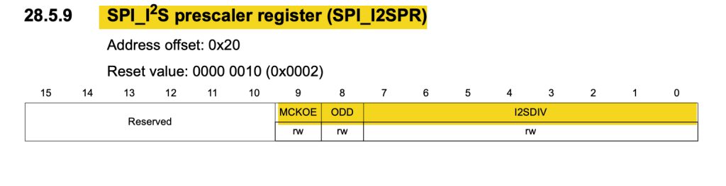
	/*Set the prescaler and ODD values*/
	SPI3->I2SPR=(3<<SPI_I2SPR_I2SDIV_Pos)|(1<<SPI_I2SPR_ODD_Pos);
Enable Master clock output:
	/*Enable Master Clock output*/
	SPI3->I2SPR|=SPI_I2SPR_MCKOE;
Enable I2S peripheral:
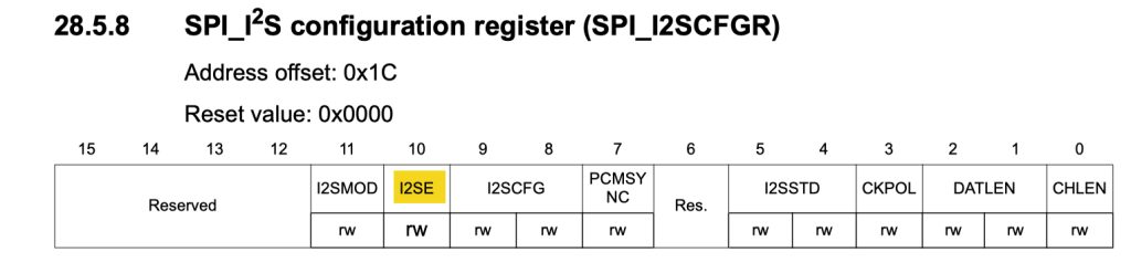
	/*Enable I2S*/

	SPI3->I2SCFGR|=SPI_I2SCFGR_I2SE;
Thats all for the intialization.
10. I2S Send Data using Polling Mode:
For sending the data over I2S, it is the same as SPI transmit mode:
void I2S_SendData(uint16_t *data, uint16_t len)
{
	uint32_t i=0;

	while(i<len)
	{
		/*Wait until TXE is set*/
		while(!(SPI3->SR & (SPI_SR_TXE))){}

		/*Write the data to the data register*/
		SPI3->DR = data[i];
		i++;
	}
	/*Wait until TXE is set*/
	while(!(SPI3->SR & (SPI_SR_TXE))){}

	/*Wait for BUSY flag to reset*/
	while((SPI3->SR & (SPI_SR_BSY))){}

	/*Clear OVR flag*/
	(void)SPI3->DR;
	(void)SPI3->SR;
}
Thats all for the I2S.c source file.
In main.c file for testing purposes:
#include "delay.h"
#include "stdlib.h"
#include "i2s.h"

#define dataSize 10
uint16_t data[dataSize] = {0x1111, 0x2222, 0x3333, 0x4444, 0x5555, 0x6666, 0x7777, 0x8888, 0x9999, 0xAAAA};


int main(void)
{
	delay_init(168000000);
	I2S3_Pins_Init();
	I2S3_Init();

	while(1)
	{
		I2S_SendData(data, dataSize);
		delay(1);
	}


}
11. Results:
By connecting logic analyzer to the clock, data and word select, you should get the following:

Since have successfully transmitted data over I2S bus.
Next, we shall use DMA to keeo transmitting the data.
Add Comment