
In this guide, we shall configure the ADC of STM32WB55 to acquire analog data from analog sensor.
In this guide, we shall cover the following:
- What is ADC.
- Driver Development.
- Results.
1. What is ADC:
In electronics, an analog-to-digital converter (ADC, A/D, or A-to-D) is a system that converts an analog signal, such as a sound picked up by a microphone or light entering a digital camera, into a digital signal that can be read by STM32.
ADCs can vary greatly between microcontroller. The ADC on the STM32F103 is a 12-bit ADC meaning it has the ability to detect 4096(2^12) discrete analog levels (which is also called Resolution). Some microcontrollers have 8-bit ADCs (2^8 = 256 discrete levels) and some have 16-bit ADCs (2^16 = 65,536 discrete levels).
The way an ADC works is fairly complex. There are a few different ways to achieve this feat (see Wikipedia for a list), but one of the most common technique uses the analog voltage to charge up an internal capacitor and then measure the time it takes to discharge across an internal resistor. The microcontroller monitors the number of clock cycles that pass before the capacitor is discharged. This number of cycles is the number that is returned once the ADC is complete. Other methods used called Successive-approximation ADC which you can read about it in details from this wikipedia page (Link).
1.2 Relating ADC Value to Voltage
The ADC reports a ratio metric value. This means that the ADC assumes 3.3V is 4095 and anything less than 3.3V will be a ratio between 3.3V and 4095.
For example if the sensor has output voltage of 1.66V hence the ADC output will be (4095/3.3)*1.66=2059.
2. Driver Development:
We start off by creating new project with name of ADC_Cont. Refer to this guide for how to create new project and clock setup.
From the schematics of STM32WB55, the arduino connectors, the analog section (A0 to A5):
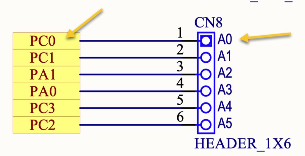
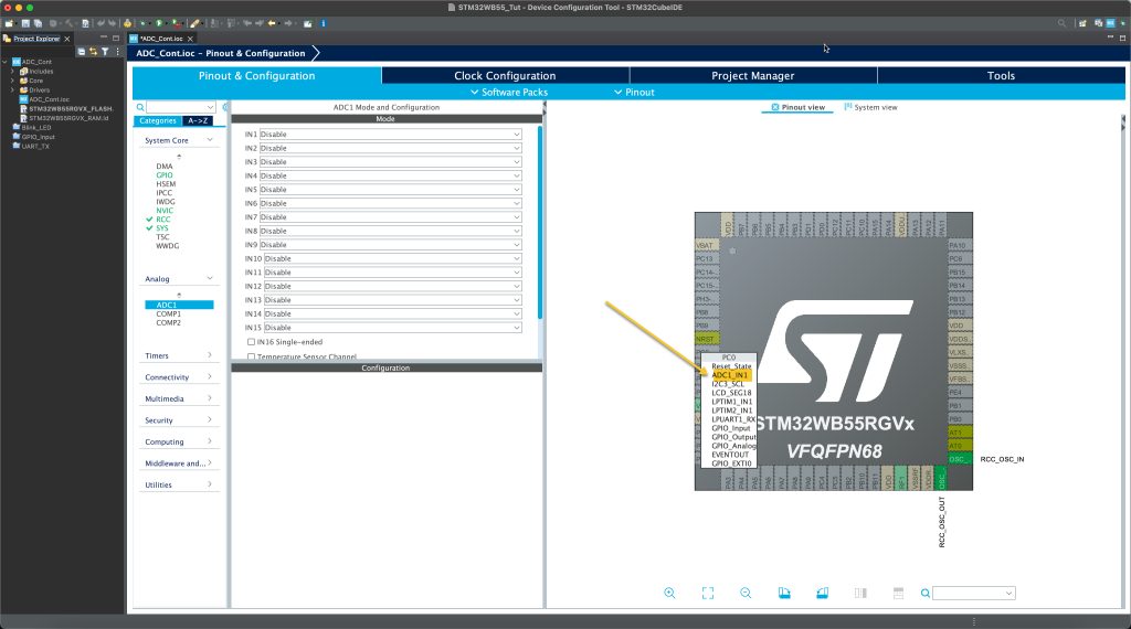
We can find that A0 is connected to PC0, hence enable PC0 as analog mode as following:
Enable IN1 as single ended as following:
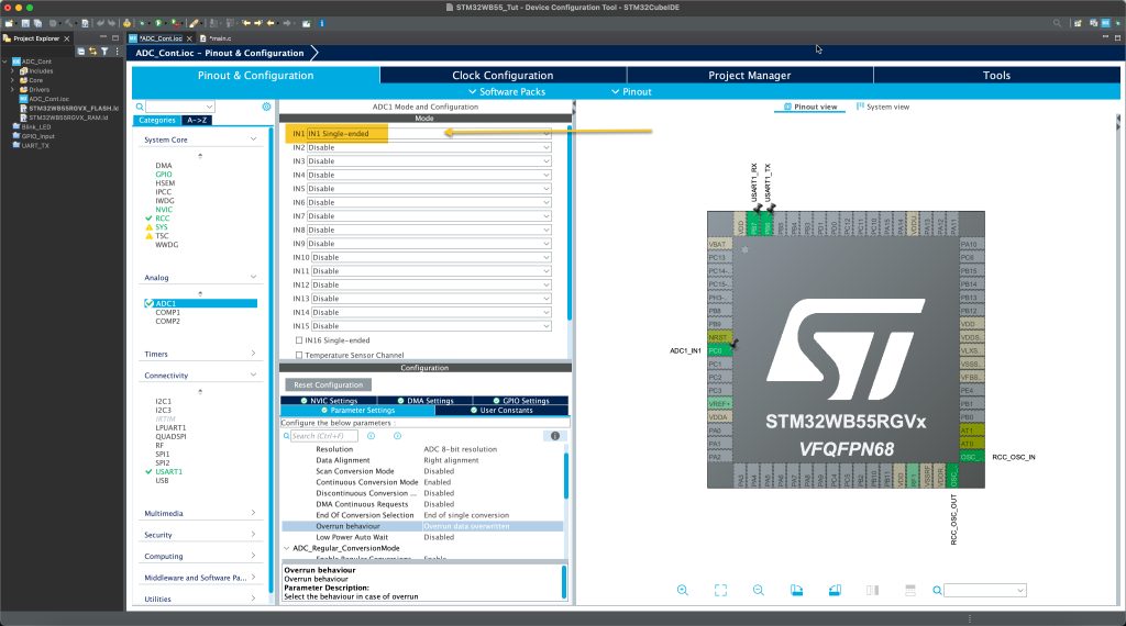
Configure the ADC parameters as following:
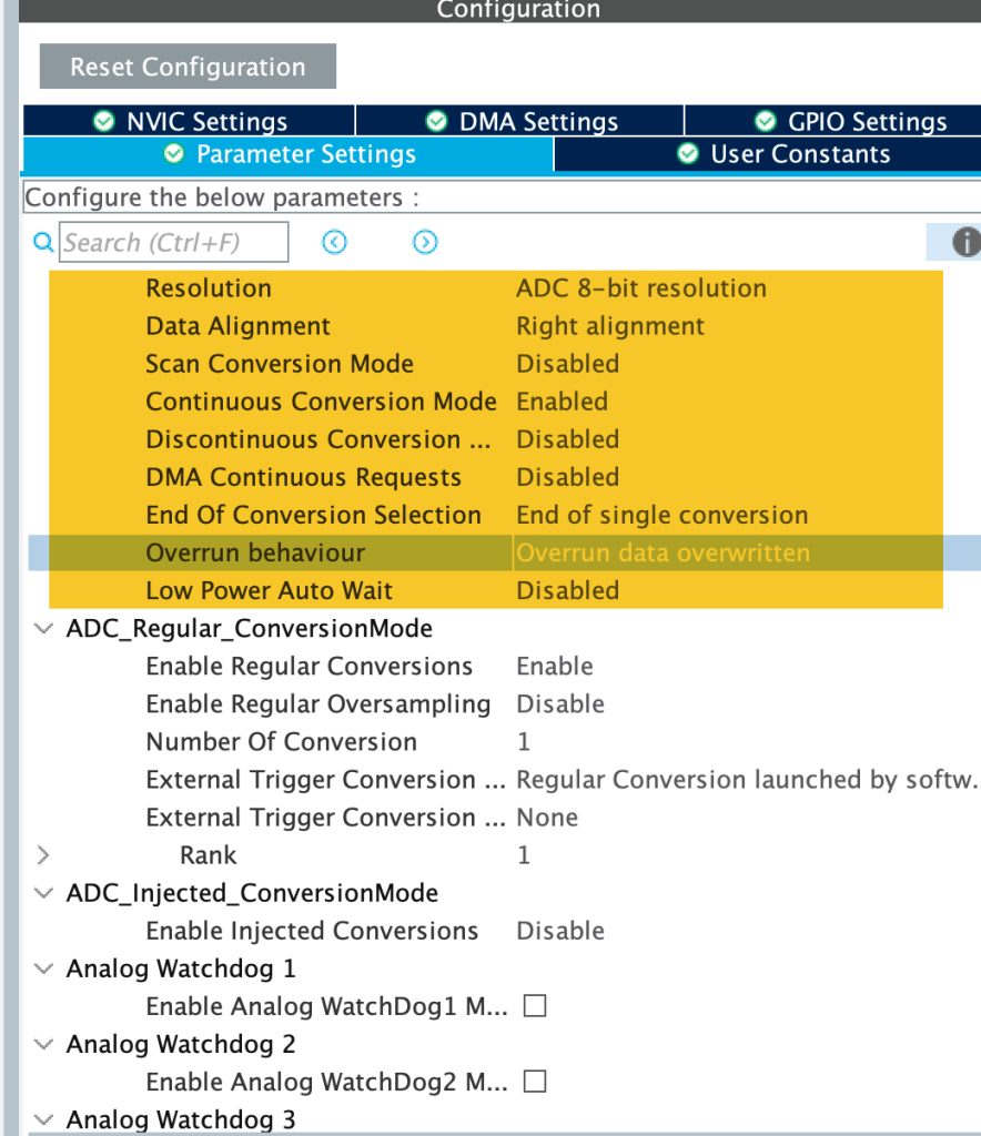
Set the ADC parameters as following:
- Set the resolution to be 8-bit.
- Enable Continuous Conversion Mode.
- Overrun behaviour to be overwritten.
Also, enable UART to print to terminal. To enable the UART, please refer to this guide.
That all for the configuration. Save the project and this will generate the code.
In user begin includes, include the stdio for printf:
/* USER CODE BEGIN Includes */
#include "stdio.h"
/* USER CODE END Includes */
In user code begin PV, declare a variable to hold the ADC results:
/* USER CODE BEGIN PV */
uint8_t adc_data;

/* USER CODE END PV */
In user code begin 0:
int __io_putchar(int ch)
{
	HAL_UART_Transmit(&huart1, &ch, 1, 10);
	return ch;
}
/* USER CODE END 0 */
This will retarget printf to print data over serial port.
In user code begin 2:
Enable the ADC as following:
  /* USER CODE BEGIN 2 */
  HAL_ADC_Start(&hadc1);
  /* USER CODE END 2 */
In user code begin 3:
	  adc_data=HAL_ADC_GetValue(&hadc1);
	  printf("ADC Value = %d \r\n", adc_data);
HAL_Delay(500);- Get the ADC by calling HAL_ADC_GetValue.
- Printf the ADC data to terminal.
- Delay by a half second.
Save, build and run the project on your Nucleo WB55.
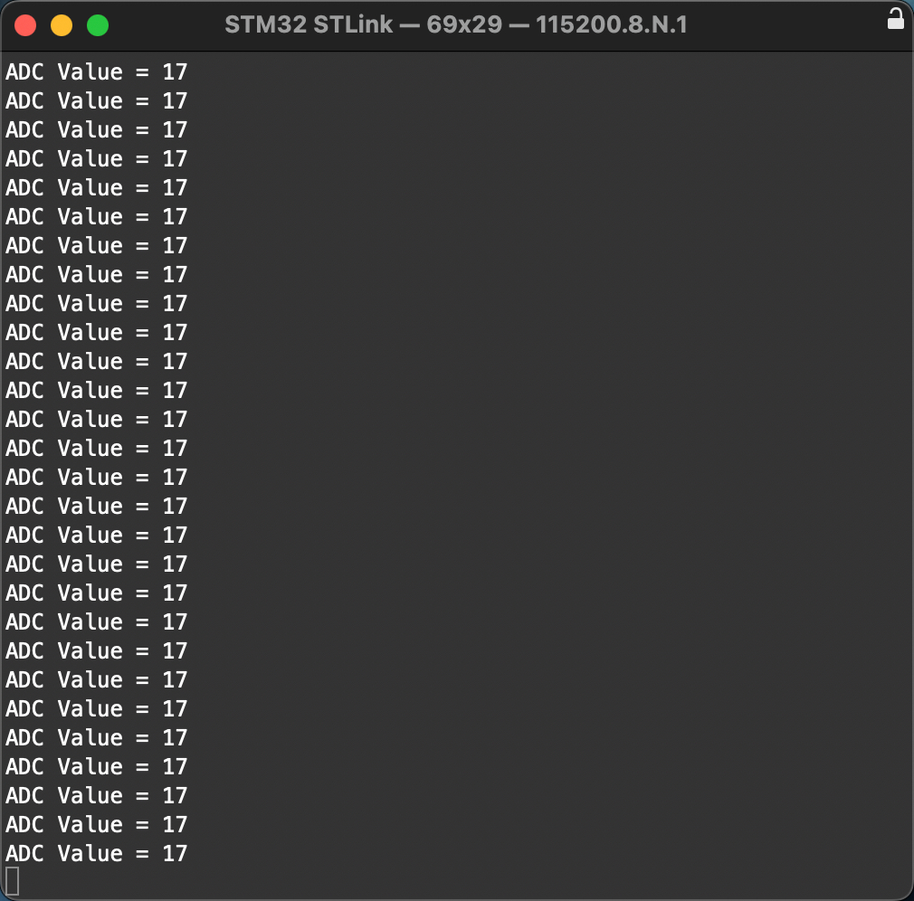
3. Results:
Open your terminal, set the baud rate to 115200 and you should get something similar to this:
Next, we shall start developing the BLE Application.
Happy coding 😉
2 Comments
I tried this on a WB55 and it didn’t work. It would only read the ADC once, then the value remained the same.
Did you enabled continuous conversion mode?
Add Comment