
In this guide series, we shall see how to work with STM32WB55 and blink the on boards LEDs and later, we shall build BLE application.
In this guide, we shall cover the following:
- Features of STM32WB55.
- Blinking on boards LEDs.
- Results.
1. Features of STM32WB55:
- Include ST state-of-the-art patented technology
- Radio
- 2.4 GHz
- RF transceiver supporting Bluetooth® 5.4 specification, IEEE 802.15.4-2011 PHY and MAC, supporting Thread 1.3 and Zigbee® 3.0
- RX sensitivity: -96 dBm (Bluetooth® Low Energy at 1 Mbps), -100 dBm (802.15.4)
- Programmable output power up to +6 dBm with 1 dB steps
- Integrated balun to reduce BOM
- Support for 2 Mbps
- Support GATT caching
- Support EATT (enhanced ATT)
- Support advertising extension
- Dedicated Arm® 32-bit Cortex® M0+ CPU for real-time Radio layer
- Accurate RSSI to enable power control
- Suitable for systems requiring compliance with radio frequency regulations ETSI EN 300 328, EN 300 440, FCC CFR47 Part 15 and ARIB STD-T66
- Support for external PA
- Available integrated passive device (IPD) companion chip for optimized matching solution (MLPF-WB-01E3, or MLPF-WB55-02E3, or MLPF-WB-02D3)
- Ultra-low-power platform
- 1.71 to 3.6 V power supply
- – 40 °C to 85 / 105 °C temperature ranges
- 13 nA shutdown mode
- 600 nA Standby mode + RTC + 32 KB RAM
- 2.1 µA Stop mode + RTC + 256 KB RAM
- Active-mode MCU: < 53 µA / MHz when RF and SMPS on
- Radio: Rx 4.5 mA / Tx at 0 dBm 5.2 mA
- Core: Arm® 32-bit Cortex®-M4 CPU with FPU, adaptive real-time accelerator (ART™ Accelerator) allowing 0-wait-state execution from flash memory, frequency up to 64 MHz, MPU, 80 DMIPS and DSP instructions
- Performance benchmark
- 1.25 DMIPS/MHz (Drystone 2.1)
- 219.48 CoreMark® (3.43 CoreMark/MHz at 64 MHz)
- Energy benckmark
- 303 ULPMark™ CP score
- Supply and reset management
- High efficiency embedded SMPS step-down converter with intelligent bypass mode
- Ultra-safe, low-power BOR (brownout reset) with five selectable thresholds
- Ultra-low-power POR/PDR
- Programmable voltage detector (PVD)
- VBAT mode with RTC and backup registers
- Clock sources
- 32 MHz crystal oscillator with integrated trimming capacitors (Radio and CPU clock)
- 32 kHz crystal oscillator for RTC (LSE)
- Internal low-power 32 kHz (±5%) RC (LSI1)
- Internal low-power 32 kHz (stability ±500 ppm) RC (LSI2)
- Internal multispeed 100 kHz to 48 MHz oscillator, auto-trimmed by LSE (better than ±0.25% accuracy)
- High speed internal 16 MHz factory trimmed RC (±1%)
- 2x PLL for system clock, USB, SAI, ADC
- Memories
- Up to 1 MB flash memory with sector protection (PCROP) against R/W operations, enabling radio stack and application
- Up to 256 KB SRAM, including 64 KB with hardware parity check
- 20x 32-bit backup register
- Boot loader supporting USART, SPI, I2C and USB interfaces
- OTA (over the air) Bluetooth® Low Energy and 802.15.4 update
- Quad SPI memory interface with XIP
- 1 Kbyte (128 double words) OTP
- Rich analog peripherals (down to 1.62 V)
- 12-bit ADC 4.26 Msps, up to 16-bit with hardware oversampling, 200 µA/Msps
- 2x ultra-low-power comparator
- Accurate 2.5 V or 2.048 V reference voltage buffered output
- System peripherals
- Inter processor communication controller (IPCC) for communication with Bluetooth® Low Energy and 802.15.4
- HW semaphores for resources sharing between CPUs
- 2x DMA controllers (7x channels each) supporting ADC, SPI, I2C, USART, QSPI, SAI, AES, timers
- 1x USART (ISO 7816, IrDA, SPI Master, Modbus and Smartcard mode)
- 1x LPUART (low power)
- 2x SPI 32 Mbit/s
- 2x I2C (SMBus/PMBus®)
- 1x SAI (dual channel high quality audio)
- 1x USB 2.0 FS device, crystal-less, BCD and LPM
- Touch sensing controller, up to 18 sensors
- LCD 8×40 with step-up converter
- 1x 16-bit, four channels advanced timer
- 2x 16-bit, two channels timer
- 1x 32-bit, four channels timer
- 2x 16-bit ultra low power timer
- 1x independent Systick
- 1x independent watchdog
- 1x window watchdog
- Security and ID
- Secure firmware installation (SFI) for Bluetooth® Low Energy and 802.15.4 SW stack
- 3x hardware encryption AES maximum 256-bit for the application, the Bluetooth® Low Energy and IEEE802.15.4
- Customer key storage/manager services
- HW public key authority (PKA)
- Cryptographic algorithms: RSA, Diffie-Helman, ECC over GF(p)
- True random number generator (RNG)
- Sector protection against R/W operation (PCROP)
- CRC calculation unit
- Die information: 96-bit unique ID
- IEEE 64-bit unique ID, possibility to derive 802.15.4 64-bit and Bluetooth® Low Energy 48-bit EUI
- Up to 72 fast I/Os, 70 of them 5 V-tolerant
- Development support
- Serial wire debug (SWD), JTAG for the application processor
- Application cross trigger with input / output
- Embedded Trace Macrocell™ for application
- ECOPACK2 compliant packages

2. Blinking on Board LEDs:
We start off by opening STM32CubeIDE:
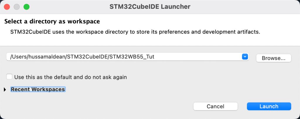
Then, it will ask for a workspace, select an appropriate workspace and click on Launch
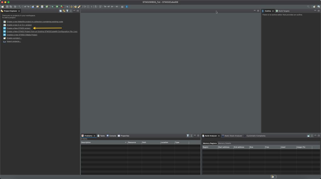
Create new STM32 Project:
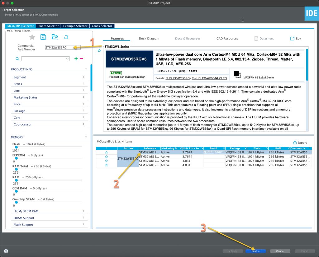
Follow these steps:
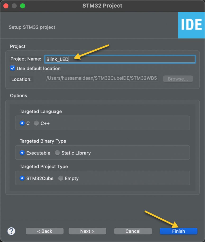
Give the project a name and click on finished:
It will start the CubeMX for the peripheral configuration.
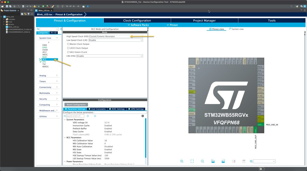
From Pinout and Configuration, open System Core then RCC:
Set the HSE to be external Ceramic oscillator.
Now, open Clock Configuration tab and setup the clock as following:
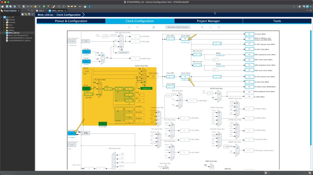
Make sure that the input frequency is 32MHz since the WB55 Nucleo has 32MHz on board oscillator.
That all for the clock setup.
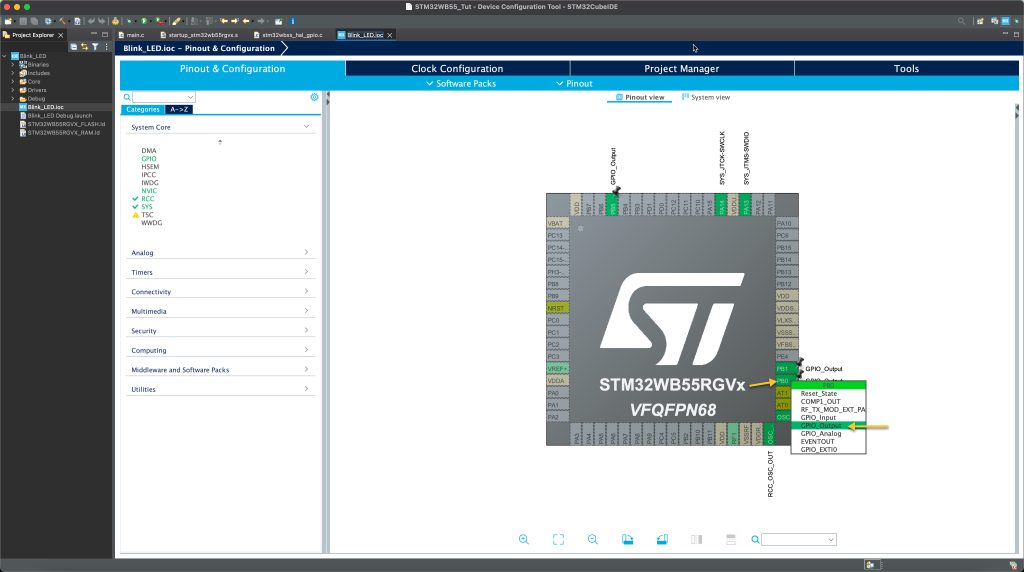
Now, we shall configure the GPIO:
From the schematic of the STM32WB55 Nucleo, we can find the following:

It has three on board LEDs connected to PB0, PB1 and PB5:
Set the pins as GPIO output as following:
Now, clock on save to generate the code.
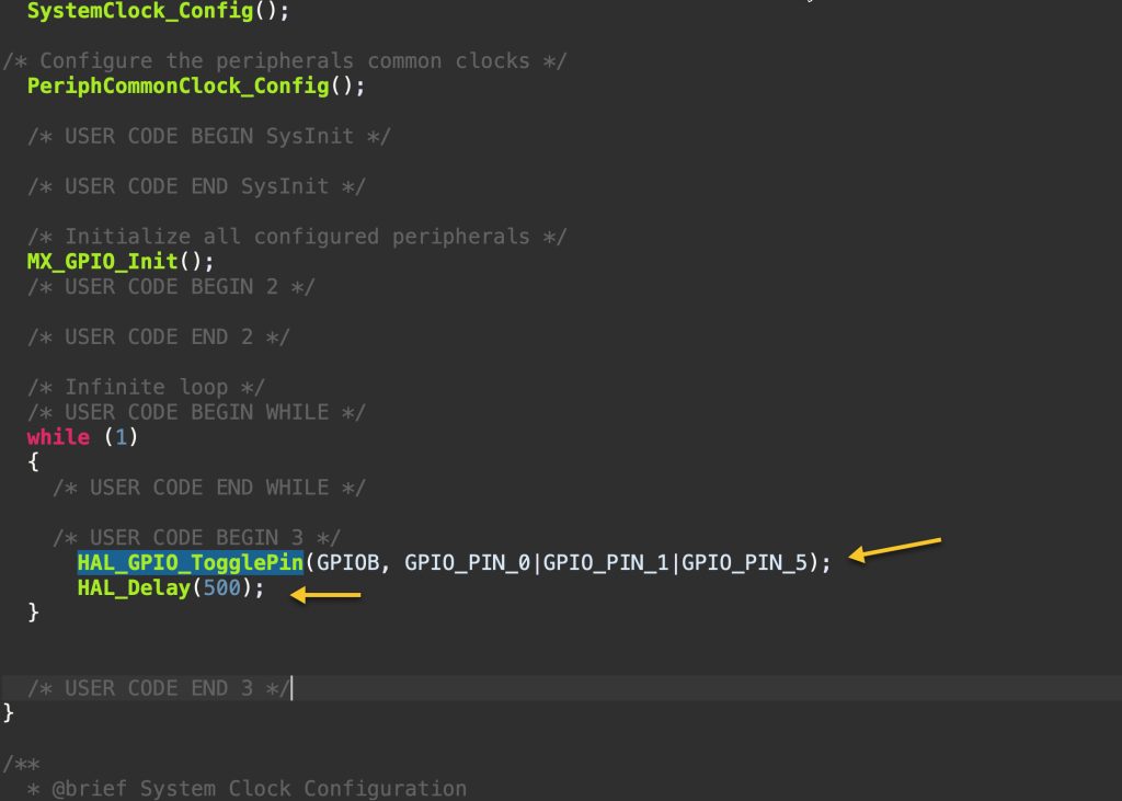
Now, in main.c:
In user begin code 3, add the following:
	  HAL_GPIO_TogglePin(GPIOB, GPIO_PIN_0|GPIO_PIN_1|GPIO_PIN_5);
	  HAL_Delay(500);
As following:
Save the code, build it and run on the Nucleo board.
3. Results:
After uploading the code, you should get this:
Stay tuned 😉
Happy coding 🙂
Add Comment