In this guide series, we shall see how to use STM32 to control various types of motors. The first type of motor is servo motor.
In this guide, we shall cover the following the following:
- What is servo motor.
- Construction of servo motor.
- Connection.
- Developing the driver.
- Results.
1. What is Servo Motor:
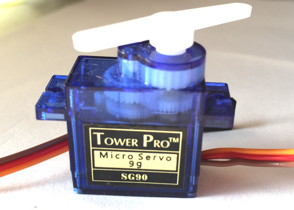
A servomotor is a rotary actuator or linear actuator that allows for precise control of angular or linear position, velocity and acceleration.[1] It consists of a suitable motor coupled to a sensor for position feedback. It also requires a relatively sophisticated controller, often a dedicated module designed specifically for use with servomotors. (Wikipedia link).
The servo motor used in our guide has three wires: red, brown and orange.
| Wire color | Function |
| Red | Vcc (4~6V) |
| Brown | GND |
| Orange | Signal |

2. Construction of Servo Motor:
The construction of the servo motor is shown in the figure below:
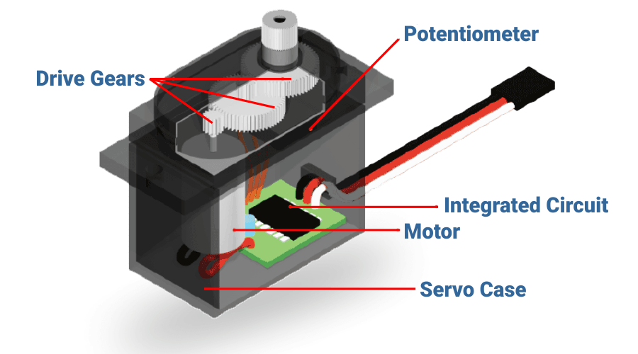
Typically, the servo motor is consist of the following parts:
- Drive great to decrease the rotation speed and increase the torque output of the motor.
- Feedback in form of potentiometer or encoder to get the current position of the putout shaft.
- Integrated circuit which compares the desired angle with the current angle and adjust the position accordingly.
- Motor which is responsible for the movement of the servo motor and it could be either DC or AC.
In this guide, we shall use DC version commonly used by RC vehicles and drones.
3. Connection:
In this guide, we need the following
- STM32F411 Nucleo
- SG90 microservo
- Hock-up wires
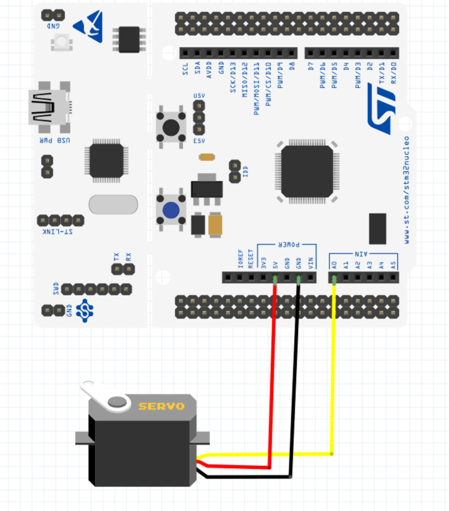
| Servo Motor | STM32F411 Nucleo-64 |
| Red | 5V |
| Brown | GND |
| Orange | PA0 |
4. Developing the Driver:
Before developing the driver, we need to understand the required pulse to control the servo motor.
In order to control the angle of the servo motor, a PWM signal of frequency 50Hz (20mS period) needed to be applied to the signal pin on the servo motor. to determine the angle of the servo as following:
| Angle | Duty Cycle (Period) |
| 0 | 5% (1mS) |
| 90 | 7.5% (1.5mS) |
| 180 | 10%(2mS) |
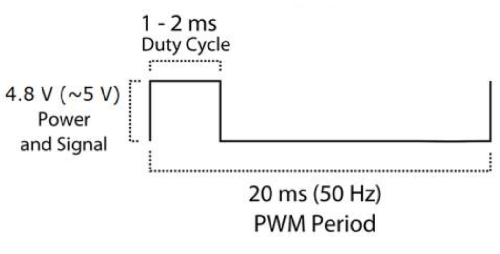
However, in reality, the servo requires signal duration of 0.65ms for 0 position and 2.4ms for 180 degree position with frequency of 50Hz.
After having the basic information, we can start with developing the driver.
We start off by creating new source and header file with name of servo.c and servo.h respectively.
Within the header file, include the header guard as following:
#ifndef SERVO_H_
#define SERVO_H_


#endif /* SERVO_H_ */
Within the header guard, include the stdint library as following:
#include "stdint.h"
Declare the following function:
/* @Brief This function shall initial GPIOA Pin 0 to control the Servo motor
 * @Param Nothing
 * @Return Nothing
 * */
void Servo_Pin_Init(void);
The function will initialize PA0 to work as PWM signal and the function takes no argument and returns nothing.
/* @Brief This function shall initial TIM2 of STM32F4 to generate 50Hz PWM signal
 * @Param freq which is the bus frequency that connected to TIM2 in MHz
 * @Return Nothing
 * */
void Servo_TIM2_Init(uint16_t freq);
This function shall setup timer2 to work as PWM mode to generate PWM signal and take frequency as parameter in MHz and returns nothing.
/* @Brief This function shall set the angle of the servo motor
 * @Param angle in degrees
 * @Return nothing
 * */
void ServoSetAngle(uint8_t angle);
This function will set the angle of the servo motor. The function takes angle as argument and returns nothing.
Hence, the header file as following:
#ifndef SERVO_H_
#define SERVO_H_


#include "stdint.h"

/* @Brief This function shall initial GPIOA Pin 0 to control the Servo motor
 * @Param Nothing
 * @Return Nothing
 * */
void Servo_Pin_Init(void);

/* @Brief This function shall initial TIM2 of STM32F4 to generate 50Hz PWM signal
 * @Param freq which is the bus frequency that connected to TIM2 in MHz
 * @Return Nothing
 * */
void Servo_TIM2_Init(uint16_t freq);


/* @Brief This function shall set the angle of the servo motor
 * @Param angle in degrees
 * @Return nothing
 * */
void ServoSetAngle(uint8_t angle);


#endif /* SERVO_H_ */
In the source file, we start include the following header file:
#include "servo.h"
Also, include STM32F4xx main header file:
#include "stm32f4xx.h"
Before that, please check this guide for how to configure the timer in PWM mode.
Declare a macro to hold the alternate function number:
#define TIM2_AF 0x01
For the GPIO initialization:
void Servo_Pin_Init(void)
{
	/*Enable clock access to GPIOA*/
	RCC->AHB1ENR|=RCC_AHB1ENR_GPIOAEN;

	/*Set PA0 to alternate function*/
	GPIOA->MODER|=GPIO_MODER_MODE0_1;
	GPIOA->MODER&=~GPIO_MODER_MODE0_0;

	/*Set the GPIO speed to maximum*/
	GPIOA->OSPEEDR|=GPIO_OSPEEDER_OSPEEDR0;

	/*Set which alternate function */
	GPIOA->AFR[0]|=(TIM2_AF<<GPIO_AFRL_AFSEL0_Pos);

}
For the timer initialization:
void Servo_TIM2_Init(uint16_t freq)
{
	/*Enable clock access to TIM2*/
	RCC->APB1ENR|=RCC_APB1ENR_TIM2EN;

	/*Set the PSC and ARR values*/
	TIM2->PSC=freq-1;
	TIM2->ARR=20000-1;

	/*Set TIM2_CH1 as PWM */

	TIM2->CCMR1|=TIM_CCMR1_OC1M_2|TIM_CCMR1_OC1M_1;

	/*Enable TIM2_CH1*/
	TIM2->CCER|=TIM_CCER_CC1E;

	/*Set TIM2_CH1 to 1ms (1000)*/
	TIM2->CCR1=650;

	/*Enable TIM2*/

	TIM2->CR1|=TIM_CR1_CEN;

}
Not that we set the PSC to freq-1 which will reduce the timer frequency to 1MHz (1uS). With ARR value of 20000 which will set the period of 20000 microseconds (20ms). These values will generate 50Hz PWM signal.
We shall declare local function will convert the angle to duty cycle as following:
/* @Brief This function shall calculate the duty cycle according the required angle
 * @Param angle in degrees
 * @Return duty cycle for the required angle
 * */

static long angle_to_duty(uint8_t angle)
{
  return (9.72*angle +650);
}
For setting the angle:
void ServoSetAngle(uint8_t angle)
{
	if (angle >180){angle=180;}

	/*Set the duty cycle according to the calculation*/
	TIM2->CCR1=angle_to_duty(angle);
}
Hence, the source file as following:
#include "servo.h"

#include "stm32f4xx.h"


#define TIM2_AF 0x01


void Servo_Pin_Init(void)
{
	/*Enable clock access to GPIOA*/
	RCC->AHB1ENR|=RCC_AHB1ENR_GPIOAEN;

	/*Set PA0 to alternate function*/
	GPIOA->MODER|=GPIO_MODER_MODE0_1;
	GPIOA->MODER&=~GPIO_MODER_MODE0_0;

	/*Set the GPIO speed to maximum*/
	GPIOA->OSPEEDR|=GPIO_OSPEEDER_OSPEEDR0;

	/*Set which alternate function */
	GPIOA->AFR[0]|=(TIM2_AF<<GPIO_AFRL_AFSEL0_Pos);

}


void Servo_TIM2_Init(uint16_t freq)
{
	/*Enable clock access to TIM2*/
	RCC->APB1ENR|=RCC_APB1ENR_TIM2EN;

	/*Set the PSC and ARR values*/
	TIM2->PSC=freq-1;
	TIM2->ARR=20000-1;

	/*Set TIM2_CH1 as PWM */

	TIM2->CCMR1|=TIM_CCMR1_OC1M_2|TIM_CCMR1_OC1M_1;

	/*Enable TIM2_CH1*/
	TIM2->CCER|=TIM_CCER_CC1E;

	/*Set TIM2_CH1 to 1ms (1000)*/
	TIM2->CCR1=650;

	/*Enable TIM2*/

	TIM2->CR1|=TIM_CR1_CEN;

}

/* @Brief This function shall calculate the duty cycle according the required angle
 * @Param angle in degrees
 * @Return duty cycle for the required angle
 * */

static long angle_to_duty(uint8_t angle)
{
  return (9.72*angle +650);
}


void ServoSetAngle(uint8_t angle)
{
	if (angle >180){angle=180;}

	/*Set the duty cycle according to the calculation*/
	TIM2->CCR1=angle_to_duty(angle);
}
In main.c:
#include "servo.h"
#include "delay.h"
int pos;
int main(void)
{

	Servo_Pin_Init();
	Servo_TIM2_Init(16);
	delay_init(16000000);

	while(1)
	{
		for (pos = 0; pos <= 180; pos += 1)
		{ // goes from 0 degrees to 180 degrees
		    // in steps of 1 degree
			ServoSetAngle(pos);              // tell servo to go to position in variable 'pos'
		    delay(15);                       // waits 15ms for the servo to reach the position
		}
		for (pos = 180; pos >= 0; pos -= 1)
		{ // goes from 180 degrees to 0 degrees
			ServoSetAngle(pos);              // tell servo to go to position in variable 'pos'
		    delay(15);                       // waits 15ms for the servo to reach the position
		}


	}

}
For the delay function, please refer to this guide.
5. Results:
Happy coding 🙂
Add Comment