In the previous guide (here), we took a look at the STM32G070 features and we were able to blink and LED using HAL. In this guide, we shall toggle the LED using pushbutton connected to out STM32G070.
In this guide, we shall cover the following :
- Input modes.
- Configure the GPIO as input with internal pull up resistor.
- Hardware Setup.
- Code.
- Results.
1. Input Modes:
GPIO input modes include
- high impedance
- pull-up
- pull-down
Floating, High Impedance, Tri-Stated
Floating, high impedance, and tri-stated are three terms that mean the same thing: the pin is just flopping in the breeze. Its state is indeterminate unless it is driven high or low externally. You only want to configure a pin as floating if you know it will be driven externally. Otherwise, configure the input using pulling resistors.
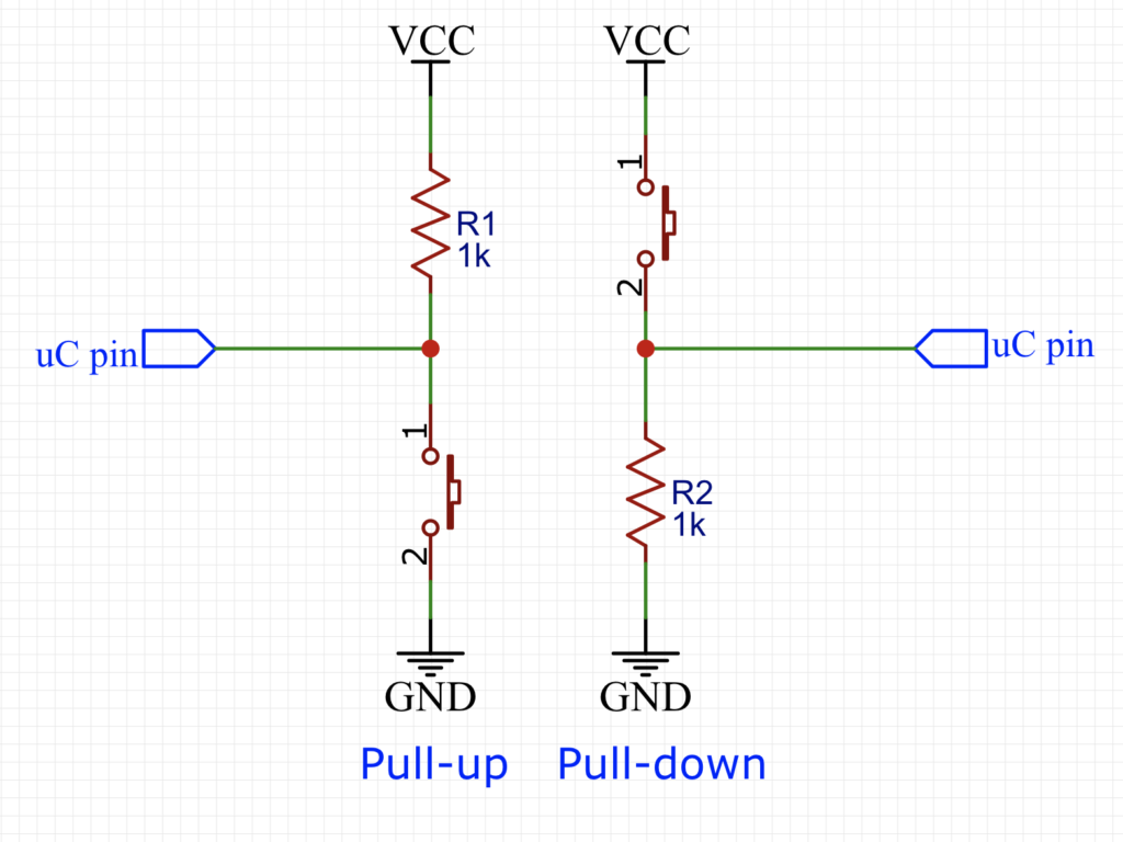
Pull Up/Down
If an input is configured with an internal pull-up, it will be high unless it is externally driven low. Pull-down inputs do the opposite ( they’re low unless driven high).
2. Configure the GPIO as Input with Internal Pull up resistor:
We start with the same process as in the previous guide we create a new project with name of GPIO_Input.
- Enable PA0 as Output.
Now Enable PA0 as input:
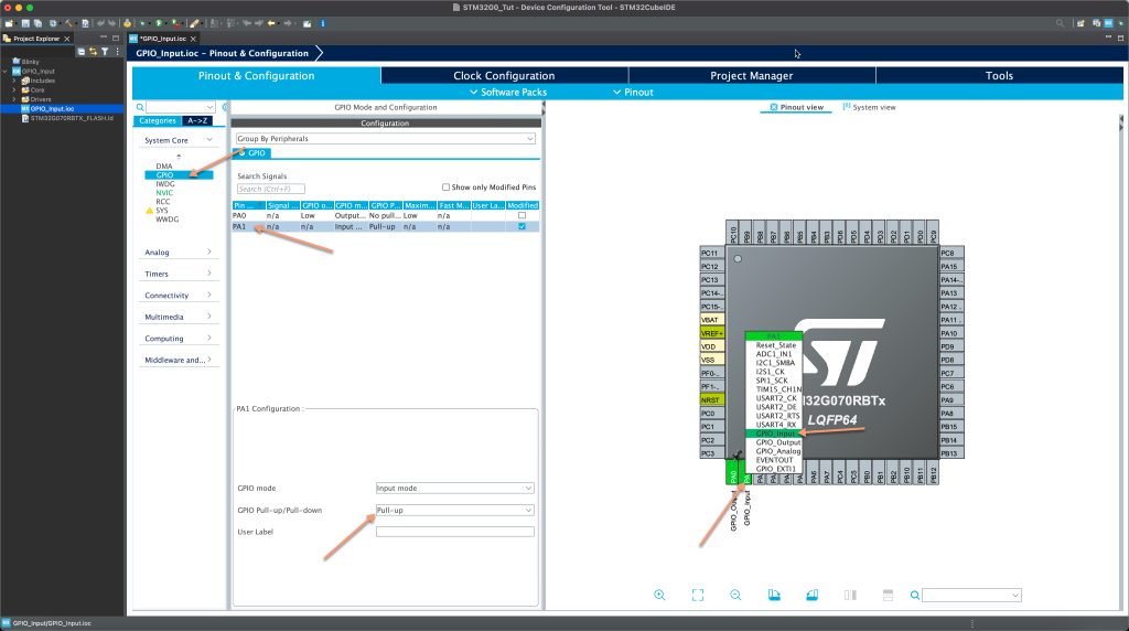
After setting PA1 as input, from System Core, open GPIO, select PA1 and set the Pull-up mode as shown in the figure above.
Now save the project to generate the code.
3. Hardware Setup:
Since we are using the internal pull up resistor, we can connect the push button directly to out MCU without using external components as shown in the figure below:

Note:
The internal pull up pull down resistors are relatively high values which is not recommended to be used in case there are interference from the environment.
4. Code:
At use code begin 3, preform the following steps:
- Check if the button is pressed, if yer:
- Toggle the LED.
- Wait for 10ms for debounce effect.
- wait until the button is released.
Hence, the code as following:
	  if((HAL_GPIO_ReadPin(GPIOA, GPIO_PIN_1))==RESET)
	  {
		  /*Toggle the pin state*/
		  HAL_GPIO_TogglePin(GPIOA, GPIO_PIN_0);
		  /*Delay by 10ms to ensure stability*/
		  HAL_Delay(10);
		  /*Wait until the button is released*/
		  while((HAL_GPIO_ReadPin(GPIOA, GPIO_PIN_1))==RESET)
		  {
			  /*Do nothing wasting CPU cycles*/
		  }
	  }
5. Results:
Upload the code to your board and press the button, you should see the LED toggle with each press.
Happy coding 😉
Add Comment