In this new guide series, we shall take a look at CANBus, brief history, message format of the CANbus and its feature within STM32F446.
Int this guide, we shall cover the following:
- What is CANBus and its feature.
- Type of CANBus
- Message format of the CANBus.
- CAN Peripheral feature within STM32F446.
- Required hardware.
- Connection.
- Environment setup.
1. What is CANBus and its Features:
CANBus, or Controller Area Network Bus, is a robust and widely used communication protocol in the field of automotive and industrial applications. Developed by Bosch in the mid-1980s, CANBus was designed to facilitate communication between various electronic control units (ECUs) within a vehicle and industrial systems. It has since become a standard in many industries due to its reliability, real-time capabilities, and flexibility.
Key features of CANBus include:
- Multi-Master Communication: CANBus supports a multi-master communication architecture, allowing multiple ECUs to transmit and receive messages on the bus simultaneously. This makes it suitable for systems with distributed control.
- Asynchronous and Event-Driven: Communication on the CANBus is event-driven, meaning that ECUs only transmit data when there is a change in the data they are monitoring. This reduces bus load and enhances efficiency.
- Deterministic and Real-Time: CANBus offers deterministic communication, ensuring that messages are transmitted and received within a predictable time frame. This real-time capability is crucial in applications where timely data exchange is essential.
- Error Detection and Handling: CANBus incorporates robust error detection and handling mechanisms. It uses a cyclic redundancy check (CRC) for error detection, and in case of an error, it can retransmit the message.
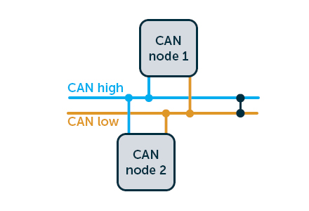
- Two-Wire Differential Bus: CANBus typically uses a two-wire differential bus (CAN_H and CAN_L) to transmit and receive signals. This differential signaling helps in noise immunity and extends the communication range.
- Standard and Extended Frames: CANBus supports both standard and extended frame formats, allowing for flexibility in the size of the identifier and the amount of data transmitted.
Applications of CANBus extend beyond the automotive industry and include industrial automation, medical equipment, aerospace, and more. It has become a de facto standard for reliable and efficient communication in systems requiring distributed control and real-time capabilities.
2. Type of CANBus:
Here are the three main types of CAN:
Low-Speed CAN
Low-Speed CAN, also known as fault-tolerant or ISO 11898-3, operates at speeds up to 125 kbps. It is designed for less critical systems like body control modules, door locks, window controls, etc., where data transmission speed isn’t vital. Its key feature is the ability to continue functioning even when one wire in the bus fails.
High-Speed CAN
High-Speed CAN, or ISO 11898-2, can reach speeds up to 1 Mbps. This type of network is suitable for more time-sensitive applications such as engine management systems and electronic braking systems due to its faster data transfer rates compared to low-speed counterparts. However, it lacks fault tolerance capabilities found in low-speed networks.
CAN FD (Flexible Data Rate)
CAN FD, introduced by Bosch in 2012, is an extension of high-speed networks with increased data rates—up to 5 Mbps—while maintaining backward compatibility with existing high-speed devices. The primary advantage of this technology lies in its ability to transmit larger payloads more efficiently than traditional CAN, making it ideal for modern vehicles with increasingly complex electronic systems.
3. Message Format of CANBus:
The message format as following:
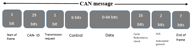
The message format of CANBus (Controller Area Network Bus) consists of several components that define how data is transmitted between nodes on the bus. Here’s an overview of the key elements in a CAN message:
- Start of Frame (SOF):
- The Start of Frame bit marks the beginning of a CAN message and is always recessive (logic 1). It helps synchronize the nodes on the bus.
- Identifier (ID):
- The Identifier field contains information about the priority and content of the message. The length of the Identifier can be either 11 bits (Standard Frame) or 29 bits (Extended Frame). The Standard Frame ID is 11 bits long, and the Extended Frame ID is 29 bits long.
- Remote Transmission Request (RTR):
- The Remote Transmission Request bit indicates whether the message is a data frame (RTR = 0) or a remote frame (RTR = 1). In a data frame, the node is transmitting actual data, while in a remote frame, the node is requesting data from another node.
- Control (IDE and RTR bits):
- The Identifier Extension (IDE) bit differentiates between Standard (IDE = 0) and Extended (IDE = 1) frame formats. The RTR bit, in conjunction with the identifier, specifies whether the frame is a data frame or a remote frame.
- Data Length Code (DLC):
- The Data Length Code field specifies the number of bytes of data in the Data field. It can range from 0 to 8 bytes.
- Data Field (0-8 bytes):
- The Data field contains the actual data being transmitted. The size of this field is determined by the DLC.
- CRC (Cyclic Redundancy Check):
- The CRC field contains a cyclic redundancy check sequence, which is used for error detection.
- ACK (Acknowledgment):
- The Acknowledgment field is used for error detection and consists of two bits: ACK and ACK delimiter.
- End of Frame (EOF):
- The End of Frame field marks the end of the message and consists of seven recessive bits.
- Interframe Space (IFS):
- The Interframe Space represents a period of time between consecutive frames during which no node is allowed to start transmitting.
The overall structure of a CAN frame is designed to ensure reliable communication, error detection, and efficient use of the communication medium. Depending on whether it’s a Standard or Extended Frame, and whether it’s a data frame or a remote frame, the fields in the frame vary.
4. CAN Peripheral Features in STM32F446:
Supports CAN protocol version 2.0 A, B Active Bit rates up to 1 Mbit/s Supports the Time Triggered Communication option
Transmission:
Three transmit mailboxes
Configurable transmit priority
Time stamp on SOF transmission
Reception:
Two receive FIFOs with three stages
Scalable filter banks:
– 28 filter banks shared between CAN1 and CAN2 for dual CAN
Identifier list feature
Configurable FIFO overrun
Time stamp on SOF reception
Time-triggered communication option
Disable automatic retransmission mode
16-bit free running timer
Time stamp sent in last two data bytes
Management
Maskable interrupts
Software-efficient mailbox mapping at a unique address space
5. Required Hardware:
We need the following hardwares:
- 2x STM32F446RE
- 2xMCP2551 CAN Transceiver Module.
- Extra components will be mentioned later in the guide.
6. Connection:
The connection of the MCP2551 as following:

| STM32F446 Nucleo-64 | MCP2551 |
| 5V | Vcc |
| GND | Gnd |
| PB8 (CANRX) | CANRX |
| PB9 (CANTX) | CANTX |
Connect Both CANH and CANL together and add 120Ohm resistor to each end.
7. Environment setup:
To setup STM32CubeIDE for register level programming, please follow the following guide.
Change type of MCU to be
STM32F446xx
Stay tune for part2.
Happy coding 🙂
Add Comment