In the previous version of WS2812 Addressable LED, we used PWM with DMA to send the data to the addressable LED. In this guide, we shall use SPI to send the data.
In this guide, we shall cover the following:
- Timing Calculation.
- Change Core Frequency.
- Delay function.
- Configure the SPI.
- WS2812 connection with STM32F4xx.
- WS2812 Driver.
- Main code.
- Code.
- Results.
1. Timing Calculation:
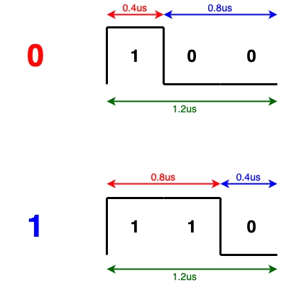
The idea is very simple. If we set the SPI baud rate at 2.5Mbits/s, each bit would represent a pulse of 0.4us.

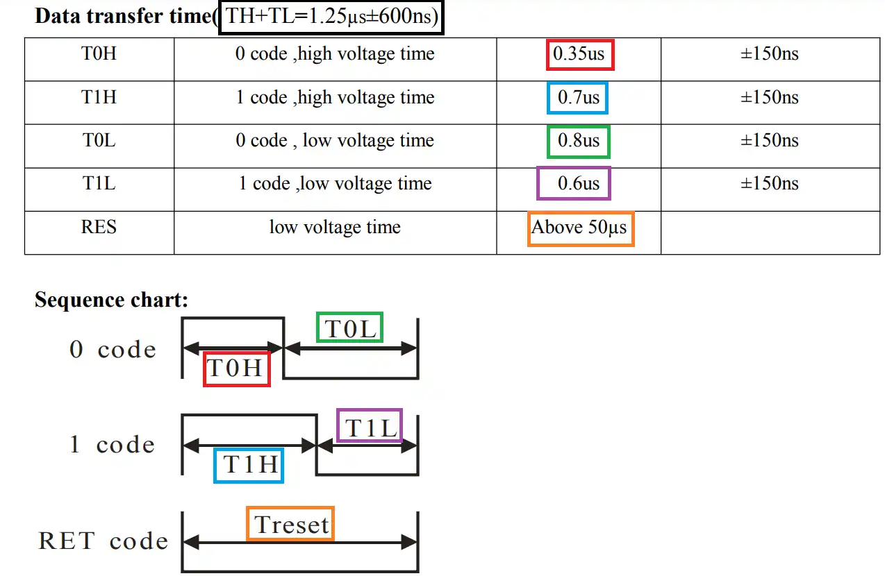
According to the datasheet of the WS2812, a bit is considered as 0 if the signal remains HIGH for 0.35us and LOW for 0.8us. And for a bit to be considered as a 1, the signal remains HIGH for 0.7us and LOW for 0.6us. Of course this is flexible with an error up to ±150ns.
Also the reset signal is supplied by pulling the data line low for more than 50us.
We will use 3 SPI bits to represent a single bit for the WS2812. The 3 SPI bits will have the time period of 1.2us (0.4*3).
2. Change the Core Frequency:
In order to achieve 2.5Mbps for the SPI, we need to set the core to be running at 80MHz. This with SPI clock divider of 32 will give us 2.5Mbps buadrate.
Create new source file with name sys_init.c:
Within the source code:
#include "stm32f4xx.h"

void SystemInit (void)
{
	#define PLL_M      4
	#define PLL_N      80
	#define PLL_P      2
	#define PLL_Q      9

	__IO uint32_t StartUpCounter = 0, HSEStatus = 0;


	  RCC->CR |= ((uint32_t)RCC_CR_HSEON);


	  do
	  {
		HSEStatus = RCC->CR & RCC_CR_HSERDY;
		StartUpCounter++;
	  } while((HSEStatus == 0) && (StartUpCounter != 3000));

	  if ((RCC->CR & RCC_CR_HSERDY) != RESET)
	  {
		HSEStatus = (uint32_t)0x01;
	  }
	  else
	  {
		HSEStatus = (uint32_t)0x00;
	  }

	  if (HSEStatus == (uint32_t)0x01)
	  {

		RCC->APB1ENR |= RCC_APB1ENR_PWREN;
		PWR->CR &= (uint32_t)~(PWR_CR_VOS);


		RCC->CFGR |= RCC_CFGR_HPRE_DIV1;


		RCC->CFGR |= RCC_CFGR_PPRE2_DIV1;


		RCC->CFGR |= RCC_CFGR_PPRE1_DIV2;


		RCC->PLLCFGR = PLL_M | (PLL_N << 6) | (((PLL_P >> 1) -1) << 16) |
					   (RCC_PLLCFGR_PLLSRC_HSE) | (PLL_Q << 24);


		RCC->CR |= RCC_CR_PLLON;


		while((RCC->CR & RCC_CR_PLLRDY) == 0)
		{
		}

		/* Configure Flash prefetch, Instruction cache, Data cache and wait state */
		FLASH->ACR = FLASH_ACR_ICEN |FLASH_ACR_DCEN |FLASH_ACR_LATENCY_7WS;


		/* Select the main PLL as system clock source */
		RCC->CFGR &= (uint32_t)((uint32_t)~(RCC_CFGR_SW));
		RCC->CFGR |= RCC_CFGR_SW_PLL;

		/* Wait till the main PLL is used as system clock source */
		while ((RCC->CFGR & (uint32_t)RCC_CFGR_SWS ) != RCC_CFGR_SWS_PLL)
		{;}
	  }
	  else
	  { /* If HSE fails to start-up, the application will have wrong clock
			 configuration. User can add here some code to deal with this error */
	  }

	/*Enable float point hardware*/
	SCB->CPACR |= ((3UL << 10*2)|(3UL << 11*2));

	/*Enable cell compensation*/
	RCC->APB2ENR|=RCC_APB2ENR_SYSCFGEN ;
	SYSCFG->CMPCR|=SYSCFG_CMPCR_CMP_PD;
	while(!((SYSCFG->CMPCR)&(SYSCFG_CMPCR_READY))){;}

}
Note: this will be called during startup, no need to be called in the main function.
3. Delay Function:
Create new source and header file with name of delay.c and delay.h respectively.
Within the header file:
#ifndef __delay__H__
#define __delay__H__

#include "stdint.h"

/*
 * @brief This function will initialize SysTick
 * to generate 1ms interrupt.
 * @param freq source frequency of SysTick.
 * @return nothing.
 * @see Generic ARM CortexM4 user guide.
 * */

void delay_init(uint32_t freq);

/*
 * @brief This function will return the current millis.
 *
 * @param nothing.
 * @return current millis.
 * */
uint64_t millis();


/*
 * @brief This function will spin lock the CPU to delay for the required
 * amount
 * @param time to be delayed in milliseconds.
 * @return nothing.
 * */
void delay(uint32_t time);


#endif
Within the source file:
#include "delay.h"
#include "stm32f4xx.h"


#define	CTRL_ENABLE					(1U<<0) /*Enable SysTick Timer*/
#define CTRL_CLKSRC					(1U<<2) /*Clock source selection*/
#define CTRL_COUNTFLAG				(1U<<16) /*Count flag bit*/
#define CTRL_TICKINT				(1U<<1) /*Interrupt enable bit*/


volatile uint64_t mil; /*volatile variable to hold the ms counter*/

void delay_init(uint32_t freq)
{

	/*Set period to be 1ms*/
	SysTick->LOAD  = (freq/1000) - 1;

	/*Clear systick current value register */
	SysTick->VAL = 0;

	/*Enable systick and select internal clk src*/
	SysTick->CTRL = CTRL_ENABLE | CTRL_CLKSRC ;

	/*Enable systick interrupt*/
	SysTick->CTRL  |= CTRL_TICKINT;

}


uint64_t millis()
	{

	__disable_irq(); /*Disable global interrupt*/

	uint64_t ml=mil; /*Get the current millis values and store in ml*/

	__enable_irq(); /*Enable global interrupt*/

	return ml;		/*Return the stored value*/
	}


/*Spin lock the CPU to delay*/
void delay(uint32_t time)
{

	uint64_t start=millis();
	while((millis() - start) < (time+1));
}

/*Interrupt handler of SysTick*/
void SysTick_Handler(void)
{
	/*Increment the counter with every interrupt*/
	mil++;
}
4. Configure SPI:
Since we need only the MOSI (Master Out Slave In) pin of the SPI, that means we need only to configure PA7 to work as SPI pin.
The parameters of the SPI as following:
- Master Mode.
- Fclk/32.
- Software slave management.
- MSB first.
- SPI Mode 0 (CPOL and CPHA are 0).
Create new source file and header file with name of SPI1.c and SPI1,h respectively.
Within the header file:
#ifndef SPI1_H_
#define SPI1_H_

#include "stdint.h"


/*
 * @brief This function will initialize SPI1 related pins.
 * @return nothing.
 * @see Pinout of datasheet for SPI pins.
 * */
void SPI1_Pins_Init(void);


/*
 * @brief This function will initialize SPI1
 * and configure it.
 * @return nothing.
 * @see reference manual SPI section.
 * */
void SPI1_Config(void);

/*
 * @brief This function will transmit data over SPI bus.
 * @param *data pointer to the data to be written.
 * @param size  size of the data to be written.
 * @return nothing.
 * */
void SPI1_Transmit(uint8_t *data,uint32_t size);


#endif /* SPI1_H_ */
The source file:
#include <SPI1.h>
#include "stm32f4xx.h"


void SPI1_Pins_Init(void)
{
	RCC->AHB1ENR|=RCC_AHB1ENR_GPIOAEN; //enable clock for GPIOA

	GPIOA->MODER|=GPIO_MODER_MODE7_1; // PA7 to alternate function mode
	GPIOA->MODER &=~(GPIO_MODER_MODE7_0);

	GPIOA->OSPEEDR|=GPIO_OSPEEDER_OSPEEDR7;

	GPIOA->AFR[0]|=(0x05<<28);
}


void SPI1_Config(void)
{
	/*Enable clock access to SPI1 module*/
	RCC->APB2ENR |= RCC_APB2ENR_SPI1EN;

	/*Set clock to fPCLK/2*/
	SPI1->CR1 &=~SPI_CR1_BR_0;
	SPI1->CR1 &=~SPI_CR1_BR_1;
	SPI1->CR1 |=SPI_CR1_BR_2;

	/*Set CPOL to 0 and CPHA to 0 (MODE0)*/
	SPI1->CR1 &=~(SPI_CR1_CPOL);
	SPI1->CR1 &=~(SPI_CR1_CPHA);

	/*Enable full duplex*/
	SPI1->CR1 &=~(SPI_CR1_RXONLY);

	/*Set MSB first*/
	SPI1->CR1 &= ~(SPI_CR1_LSBFIRST);

	/*Set mode to MASTER*/
	SPI1->CR1 |= (SPI_CR1_MSTR);

	/*Set 8 bit data mode*/
	SPI1->CR1 &= ~(SPI_CR1_DFF);

	/*Select software slave management by
	* setting SSM=1 and SSI=1*/
	SPI1->CR1 |= (SPI_CR1_SSM);
	SPI1->CR1 |= (SPI_CR1_SSI);

	/*Enable SPI module*/
	SPI1->CR1 |= (SPI_CR1_SPE);
}

void SPI1_Transmit(uint8_t *data,uint32_t size)
{
	uint32_t i=0;

	while(i<size)
	{
		/*Wait until TXE is set*/
		while(!(SPI1->SR & (SPI_SR_TXE))){}

		/*Write the data to the data register*/
		SPI1->DR = data[i];
		i++;
	}
	/*Wait until TXE is set*/
	while(!(SPI1->SR & (SPI_SR_TXE))){}

	/*Wait for BUSY flag to reset*/
	while((SPI1->SR & (SPI_SR_BSY))){}

	/*Clear OVR flag*/
	(void)SPI1->DR;
	(void)SPI1->SR;
}
As you can see, we only configure the PA7 to work as SPI, the rest is left as default state.
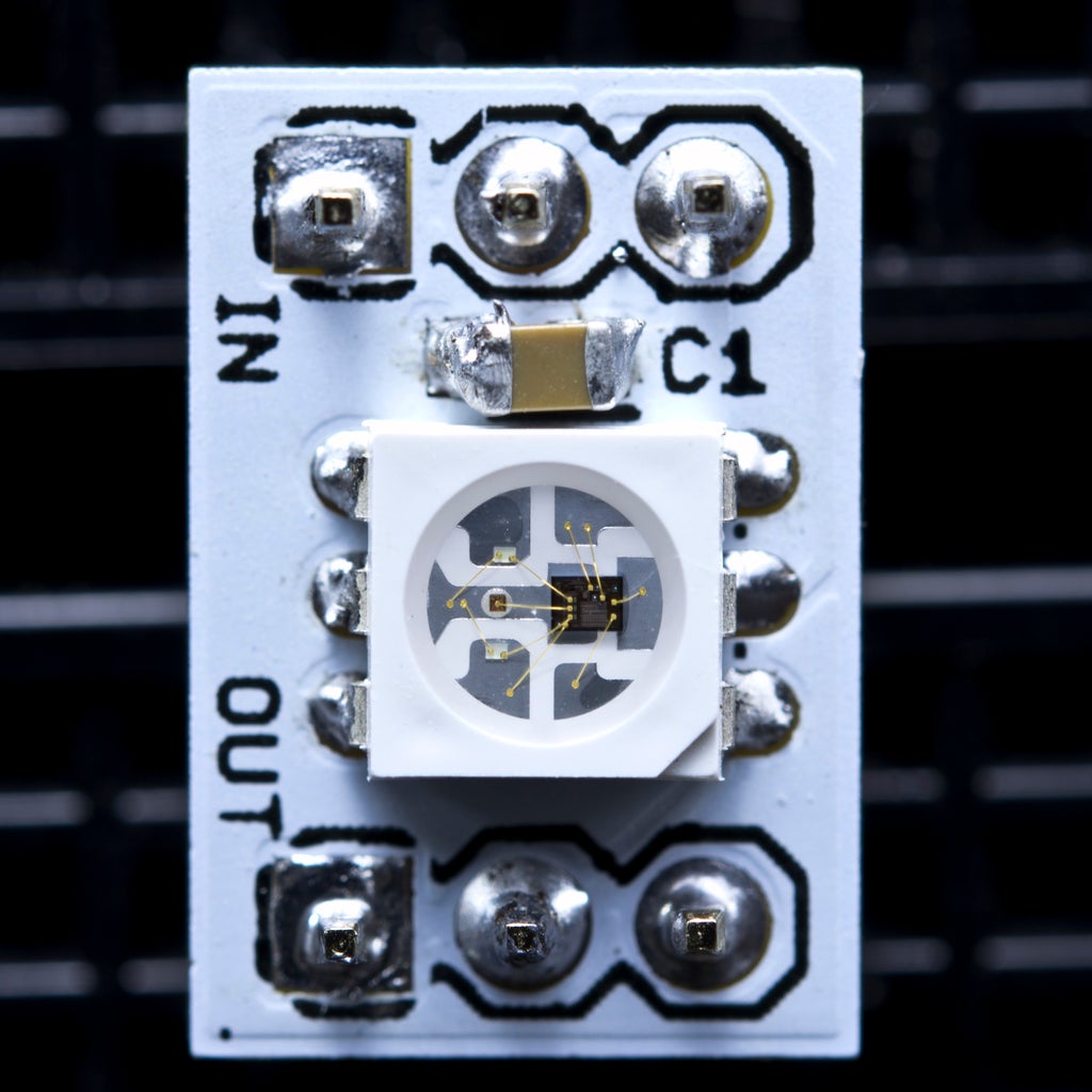
5. WS2812B Connection with STM32F4xx:
The connection as following:
6. WS2812 Driver:
Create new header file with name of WS2812.h.
Within the header file, include the header guard as following:
#ifndef WS2812_H_
#define WS2812_H_


#endif /* WS2812_H_ */
Within the header guard, include stdint library as following:
#include "stdint.h"
Declare number of the LEDs as following (change according to number of LEDs in your setup):
/*Set number of LED in the string*/
#define NUM_OF_LEDs 24
Declare set brightness function:
/*
 * @brief This function will set the LED Brightness.
 * @param brightness value.
 * @return nothing.
 * */
void WS2812_Set_Brightness(uint8_t value);
This function will set the LED brightness and takes value as argument and return nothing.
Declare set color of the LED function as following:
/*
 * @brief This function will set the LED colors value.
 * @param led: LED Number.
 * @param RED: Red color value.
 * @param GREEN: Green color value.
 * @param BLUE: Blue color value.
 * @retun nothing
 * */
void WS2812_Set_LED_Color (int led, int RED, int GREEN, int BLUE);
This function will set specific LED to the desired color. The function take the following four arguments:
- led which is led number.
- Red, Green and blue values.
The function will return nothing.
Declare set LED function as following:
/*
 * @brief This function will write the data to the LED string.
 * @param nothing.
 * @return nothing
 * */
void WS2812_Set (void);
This function will write the new data to the LED string and it takes no argument and returns nothing.
Hence, the entire header file as following:
#ifndef WS2812_H_
#define WS2812_H_

#include "stdint.h"

/*Set number of LED in the string*/
#define NUM_OF_LEDs 24

/*
 * @brief This function will set the LED Brightness.
 * @param brightness value.
 * @return nothing.
 * */
void WS2812_Set_Brightness(uint8_t value);

/*
 * @brief This function will set the LED colors value.
 * @param led: LED Number.
 * @param RED: Red color value.
 * @param GREEN: Green color value.
 * @param BLUE: Blue color value.
 * @retun nothing
 * */
void WS2812_Set_LED_Color (int led, int RED, int GREEN, int BLUE);

/*
 * @brief This function will write the data to the LED string.
 * @param nothing.
 * @return nothing
 * */
void WS2812_Set (void);


#endif /* WS2812_H_ */
Create new source file with name of WS2812.c.
Within the source file, include the following:
#include "WS2812.h"
#include "SPI1.h"
#include "delay.h"
declare brightness variable with initial value of 100 for maximum brightness:
uint8_t brightness=100;
Create two dimensional array as following:
uint8_t LED_Data[NUM_OF_LEDs][4];
For set brightness function:
void WS2812_Set_Brightness(uint8_t value)
{
	if(value>100)value=100;
	brightness=value;
}
Simply, check if the value bigger than 100, set it to 100.
For set LED color:
void WS2812_Set_LED_Color (int led, int RED, int GREEN, int BLUE)
{
	LED_Data[led][0] = led;
	LED_Data[led][1] = GREEN;
	LED_Data[led][2] = RED;
	LED_Data[led][3] = BLUE;
}
Since the have 24 arrays and each array has 4 elements, we set the first element to the number of the LED, second, third and fourth element to the color red, green and blue respectively.
The following declare function as static which can be only used within this source:
static void ws2812_spi (int GREEN, int RED, int BLUE)
{

	GREEN = GREEN*brightness/100;
	RED = RED*brightness/100;
	BLUE = BLUE*brightness/100;

	uint32_t color = GREEN<<16 | RED<<8 | BLUE;
	uint8_t sendData[24];
	int indx = 0;

	for (int i=23; i>=0; i--)
	{
		if (((color>>i)&0x01) == 1) sendData[indx++] = 0b110;  // store 1
		else sendData[indx++] = 0b100;  // store 0
	}

	SPI1_Transmit( sendData, 24);
}
First, we calculate the brightness of the LED by simply multiplying the ratio of the brightness to the desired value.
Declare local uint32_t variable to hold the color value which is 24-bit in length, hence, the variable size is 32-bit.
declare local 24 byte size buffer to hold the data to be send and index to track the data.
Store the color of the LED as mentioned in the calculation section.
Finally, transmit the data.
Finally, LED set function:
void WS2812_Set (void)
{
	for (int i=0; i<NUM_OF_LEDs; i++)
	{
		ws2812_spi(LED_Data[i][1], LED_Data[i][2], LED_Data[i][3]);
	}
	delay (1);
}
It is as simple as sending the color of the pixel from the main array.
Hence, the source code as following:
#include "WS2812.h"
#include "SPI1.h"
#include "delay.h"

uint8_t brightness=100;

uint8_t LED_Data[NUM_OF_LEDs][4];

void WS2812_Set_Brightness(uint8_t value)
{
	if(value>100)value=100;
	brightness=value;
}

void WS2812_Set_LED_Color (int led, int RED, int GREEN, int BLUE)
{
	LED_Data[led][0] = led;
	LED_Data[led][1] = GREEN;
	LED_Data[led][2] = RED;
	LED_Data[led][3] = BLUE;
}


static void ws2812_spi (int GREEN, int RED, int BLUE)
{

	GREEN = GREEN*brightness/100;
	RED = RED*brightness/100;
	BLUE = BLUE*brightness/100;

	uint32_t color = GREEN<<16 | RED<<8 | BLUE;
	uint8_t sendData[24];
	int indx = 0;

	for (int i=23; i>=0; i--)
	{
		if (((color>>i)&0x01) == 1) sendData[indx++] = 0b110;  // store 1
		else sendData[indx++] = 0b100;  // store 0
	}

	SPI1_Transmit( sendData, 24);
}

void WS2812_Set (void)
{
	for (int i=0; i<NUM_OF_LEDs; i++)
	{
		ws2812_spi(LED_Data[i][1], LED_Data[i][2], LED_Data[i][3]);
	}
	delay (1);
}
7. Main code:
In main.c code:
#include "delay.h"
#include "SPI1.h"
#include "stdlib.h"
#include "WS2812.h"


int main(void)
{
	delay_init(80000000);
	SPI1_Pins_Init();
	SPI1_Config();
	WS2812_Set_Brightness(100);

	while(1)
	{
		for (int i=0;i<NUM_OF_LEDs;i++)
		{
			srand(millis());
			WS2812_Set_LED_Color(i,random()%256,random()%256,random()%256);

			WS2812_Set();
			delay(random()%100);
		}
		delay(200);

		for (int i=NUM_OF_LEDs;i>=0;i--)
		{
			srand(millis());
			WS2812_Set_LED_Color(i,0,0,0);

			WS2812_Set();
			delay(random()%100);
		}
		delay(200);

	}

}
8. Code:
You may download the code from here:
9. Results:
Once you compiled and run the code on your board, you should get the following:
Happy coding 😉
3 Comments
Dear SIr,
Namaskar, Good Morning,
wrt to this page, as you have mentioned….
“In the previous version of WS2812 Addressable LED, we used PWM with DMA to send the data to the addressable LED. In this guide, we shall use SPI to send the data.”
Please let me know which tutorials you are refering to, I hope I have NOT missed any ONE of your tutorial lessons.
thanks for your presentations,
with warm regards,
HSR-Rao.
Hi,
it was two part series:
Part 1: https://blog.embeddedexpert.io/?p=1047
Part 2: https://blog.embeddedexpert.io/?p=1060
Dear Sir,
Thank you for your prompt and early response,
with warm regards,
HSR-Rao.
Add Comment