In this guide, we shall see how to interface addressable LED WS2812 with STM32. We shall see how the data should be send, and how to configure STM32 to communicate with these type of LED.
In this part 1, we shall cover the following
In this guide, we shall cover the following:
- WS2812
- Communication with WS2812.
- Setting up STM32 core frequency
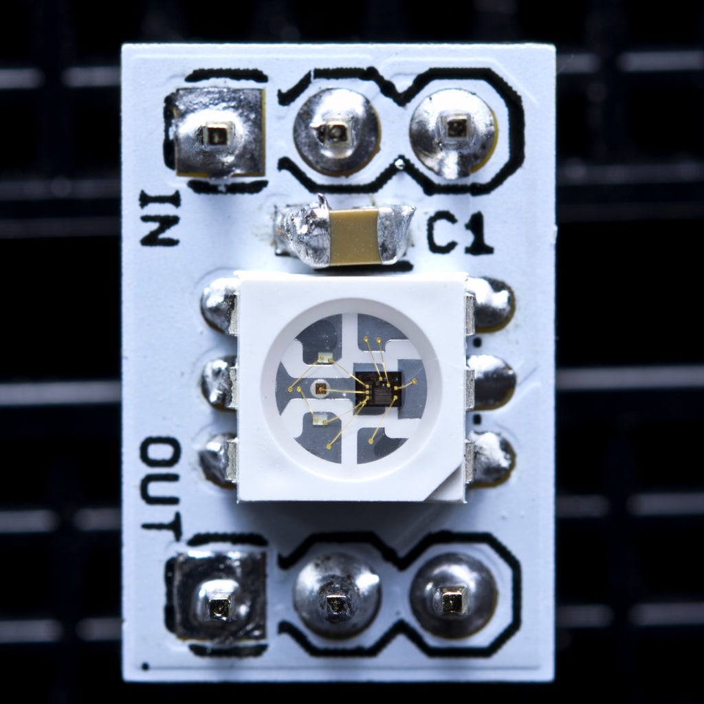
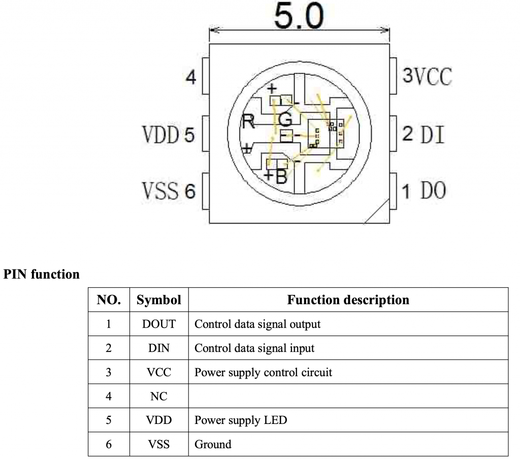
1. WS2812:
WS2812 is a intelligent control LED light source that the control circuit and RGB chip are integrated in a package of 5050 components. It internal include intelligent digital port data latch and signal reshaping amplif ication drive circuit. Also include a precision internal oscillator and a 12V voltage programmable constant curre -nt control part, effectively ensuring the pixel point light color height consistent.
The data transfer protocol use single NZR communication mode. After the pixel power-on reset, the DIN port receive data from controller, the first pixel collect initial 24bit data then sent to the internal data latch, the other data which reshaping by the internal signal reshaping amplification circuit sent to the next cascade pixel through the DO port. After transmission for each pixel,the signal to reduce 24bit. pixel adopt auto resha -ping transmit technology, making the pixel cascade number is not limited the signal transmission, only depend
on the speed of signal transmission.
LED with low driving voltage, environmental protection and energy saving, high brightness, scattering angl
e is large, good consistency, low power, long life and other advantages. The control chip integrated in LED above becoming more simple circuit, small volume, convenient installation.
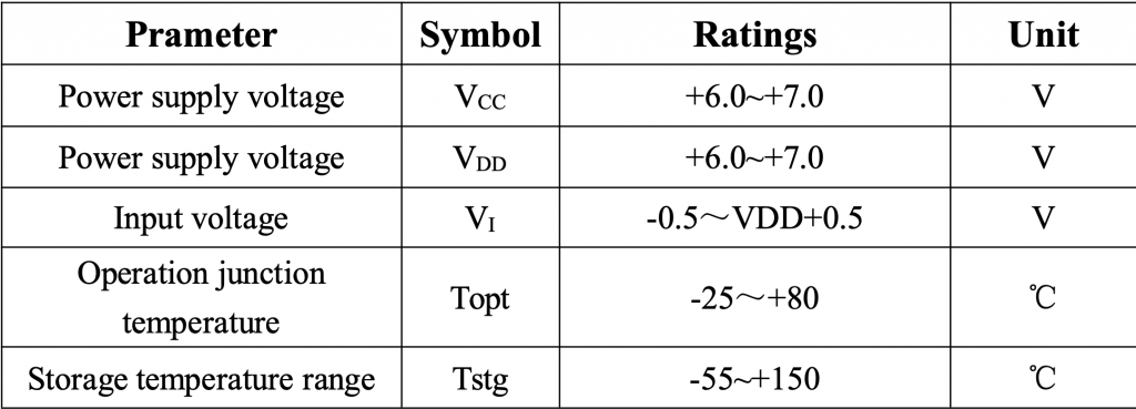
Absolute Maximum Ratings:
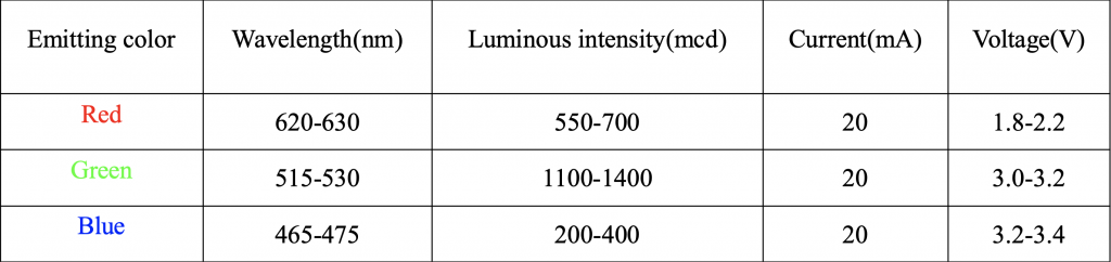
LED characteristics:
2. Communication with WS2812:
In order to communicate with WS2812, we need to used serial data. The serial shall be send as following:
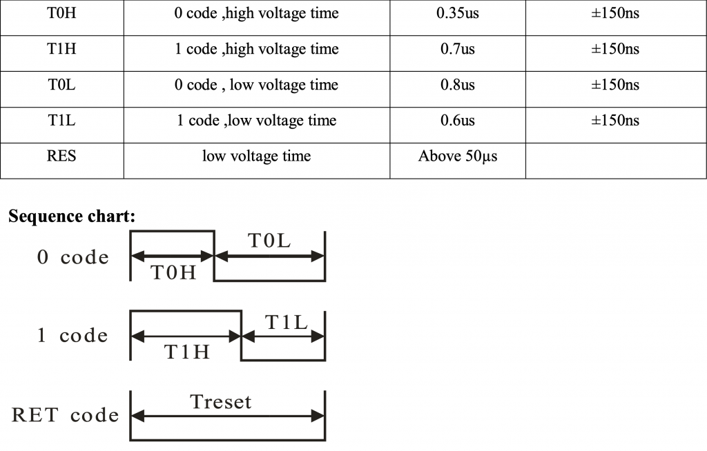
In order to send 0, the duration of high pulse is 1/3rd of the pulse and to send 1, the pulse length shall be 2/3rd of the pulse duration. To terminate the communication, the host MCU shall send low pulse for more than 50uS.
Since the T0H and T0L combined shall give duration of 125uS. Hence the PWM frequency shall be 800KHz.
For this to work, a DMA shall be used to update the duty cycle as fast as posssible.
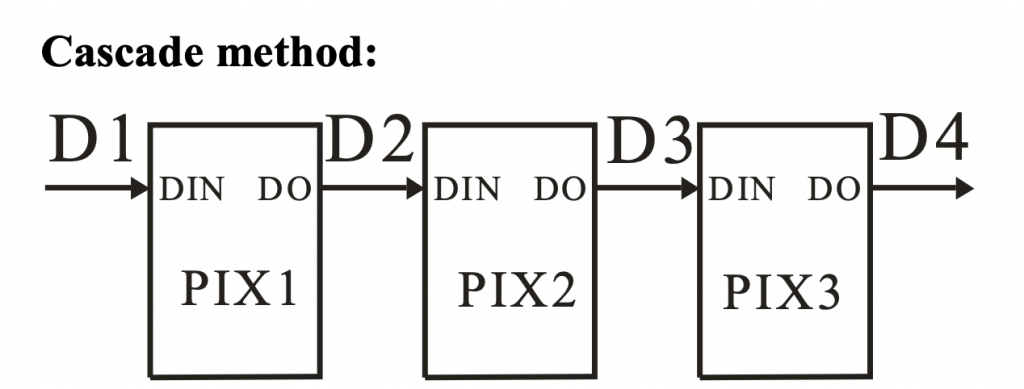
It is also possible to cascade multiple WS2812 LEDs together as following:
The transmission of the data shall be as following:
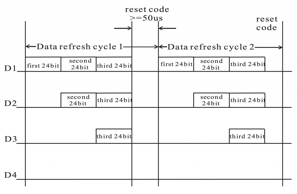
First 24-bit is for pixel 1 second 24-bit for pixel 2 and so on. The reset command is 50uS long low signal.
The composition of the 24-bit data is as following:
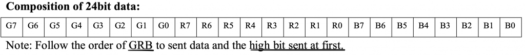
The data shall be send for green color first and MSB first.
3. Setting up STM32 Core frequency:
Since the required frequency of the PWM is 800KHz and the default frequency of STM32F4 is 16MHz, we shall boost the frequency from 16MHz to 72MHz. This will allow use to get duty cycle from 0 to 90 (0 is 0% and 90 is 100%). This will give better resolution to set the specific bit which will be 30 for 0 and 60 for 1.
In order to set the core to 72MHz (taken from this earlier topic here), the following code will set the core of STM32F411 to 72MHz.
#include "stm32f4xx.h"                  // Device header

void SysClockConfig(void) //set the core frequency to 100MHz
{
#define PLL_M      4
#define PLL_N      72
#define PLL_P      2
#define PLL_Q      4

__IO uint32_t StartUpCounter = 0, HSEStatus = 0;


  RCC->CR |= ((uint32_t)RCC_CR_HSEON);


  do
  {
    HSEStatus = RCC->CR & RCC_CR_HSERDY;
    StartUpCounter++;
  } while((HSEStatus == 0) && (StartUpCounter != 3000));

  if ((RCC->CR & RCC_CR_HSERDY) != RESET)
  {
    HSEStatus = (uint32_t)0x01;
  }
  else
  {
    HSEStatus = (uint32_t)0x00;
  }

  if (HSEStatus == (uint32_t)0x01)
  {

    RCC->APB1ENR |= RCC_APB1ENR_PWREN;
    PWR->CR &= (uint32_t)~(PWR_CR_VOS);


    RCC->CFGR |= RCC_CFGR_HPRE_DIV1;


    RCC->CFGR |= RCC_CFGR_PPRE2_DIV1;


    RCC->CFGR |= RCC_CFGR_PPRE1_DIV2;


    RCC->PLLCFGR = PLL_M | (PLL_N << 6) | (((PLL_P >> 1) -1) << 16) |
                   (RCC_PLLCFGR_PLLSRC_HSE) | (PLL_Q << 24);


    RCC->CR |= RCC_CR_PLLON;


    while((RCC->CR & RCC_CR_PLLRDY) == 0)
    {
    }

    /* Configure Flash prefetch, Instruction cache, Data cache and wait state */
    FLASH->ACR = FLASH_ACR_ICEN |FLASH_ACR_DCEN |FLASH_ACR_LATENCY_3WS;

    /* Select the main PLL as system clock source */
    RCC->CFGR &= (uint32_t)((uint32_t)~(RCC_CFGR_SW));
    RCC->CFGR |= RCC_CFGR_SW_PLL;

    /* Wait till the main PLL is used as system clock source */
    while ((RCC->CFGR & (uint32_t)RCC_CFGR_SWS ) != RCC_CFGR_SWS_PLL)
    {;}
  }
  else
  { /* If HSE fails to start-up, the application will have wrong clock
         configuration. User can add here some code to deal with this error */
  }

}
In part 2, we shall develop the driver for WS2812 and control 24 LEDs.
Happy coding 🙂
Add Comment