In the second section of part 2 of parallel port emulation, we shall see how to read the data being transmitted and display the data on LCD.
In this guide, we shall cover the following:
- Transmitter code modification.
- Receiver code.
- Connection of two STM32s.
- Code
- Results.
1. Transmitter Code Modification:
Before the code modification, take a look at this guide where it explains the I2C LCD connection and the required header and source files.
The modified transmitter code as following:
#include "stm32f4xx.h"
#include "stdint.h"
#include "stdio.h"
#include "i2c.h"
#include "LiquidCrystal_PCF8574.h"

#define data_size 	5
#define CH6 		0x06

uint32_t gpio_pattern[data_size]={200,400,100,120,150};


#define AF01		0x01

char lcd_data[60];
uint16_t counter;

int main(void)
{

	i2c_init();
	lcd_init();
	lcd_clear();
	/*GPIO Configuration*/

	/*Enable clock access to GPIOA*/
	RCC->AHB1ENR|=RCC_AHB1ENR_GPIOCEN;

	/*Set PC0 to PC7 as output*/
	GPIOC->MODER|=GPIO_MODER_MODE0_0|GPIO_MODER_MODE1_0|GPIO_MODER_MODE2_0
			|GPIO_MODER_MODE3_0|GPIO_MODER_MODE4_0|GPIO_MODER_MODE5_0|
			GPIO_MODER_MODE6_0|GPIO_MODER_MODE7_0;

	GPIOC->MODER&=~(GPIO_MODER_MODE0_1|GPIO_MODER_MODE1_1|GPIO_MODER_MODE2_1
			|GPIO_MODER_MODE3_1|GPIO_MODER_MODE4_1|GPIO_MODER_MODE5_1
			|GPIO_MODER_MODE6_1|GPIO_MODER_MODE7_1);


	/*PA8 configuration*/

	/*Enable clock access to GPIOA*/
	RCC->AHB1ENR|=RCC_AHB1ENR_GPIOAEN;

	/*Set PA8 to AF*/
	GPIOA->MODER|=GPIO_MODER_MODE8_1;
	GPIOA->MODER&=~GPIO_MODER_MODE8_0;

	/*Set PA8 to AF1*/

	GPIOA->AFR[1]|=(AF01<<GPIO_AFRH_AFSEL8_Pos);


	/*Timer configuration*/

	RCC->APB2ENR  |=  RCC_APB2ENR_TIM1EN;

	TIM1->DIER=TIM_DIER_UDE;

	TIM1->PSC=16000-1; /*16 000 000 / 16 000 =1 000*/
	TIM1->ARR=1000-1; /*1 000 / 1 000 = 10HZ*/

	TIM1->CCR1=100;

	TIM1->CCMR1|=TIM_CCMR1_OC1M_2|TIM_CCMR1_OC1M_1;

	TIM1->CCER|=TIM_CCER_CC1E;

	TIM1->BDTR|=TIM_BDTR_MOE;

	/*DMA configuration*/


	RCC->AHB1ENR|=RCC_AHB1ENR_DMA2EN;

	DMA2_Stream5->CR&=DMA_SxCR_EN;

	while((DMA2_Stream5->CR)&DMA_SxCR_EN){;}

	DMA2_Stream5->CR|=(CH6<<DMA_SxCR_CHSEL_Pos)|DMA_SxCR_MSIZE|DMA_SxCR_PSIZE|
			DMA_SxCR_MINC|DMA_SxCR_CIRC|DMA_SxCR_DIR_0;

	DMA2_Stream5->NDTR=(uint32_t)data_size;

	DMA2_Stream5->PAR=(uint32_t)(&GPIOC->ODR);

	DMA2_Stream5->M0AR=(uint32_t)(gpio_pattern);


	/*Launch DMA*/
	DMA2_Stream5->CR|=DMA_SxCR_EN;

	/*Launch Timer*/
	TIM1->CR1     |= TIM_CR1_CEN;

	srand (TIM1->CNT);

	while(1)
	{
		sprintf(lcd_data,"Data to be send:");
		setCursor(0, 0);
		lcd_send_string(lcd_data);
		setCursor(0, 1);
		counter=5-((DMA2_Stream5->NDTR));
		sprintf(lcd_data,"%d   ",gpio_pattern[counter]);
		lcd_send_string(lcd_data);

	}

}
You might noticed, we no longer randomize the data to be send and they have been fixed to certain values.
Also, the LCD part is added.
Thats all for the transmitter code modification.
2. Receiver Code:
For the receiver code, we need an extra STM32F4xx board to receive the data.
We start off by including these header file:
#include "stm32f4xx.h"
#include "i2c.h"
#include "stdio.h"
#include "LiquidCrystal_PCF8574.h"
Declare characters array to handle the display:
char str[40];
Declare volatile uint8_t variable for parallel data handling:
volatile uint8_t parallelData;
In main function:
Initialize the i2c and LCD:
int main()
{
	/*LCD Stuff*/
	i2c_init();
	lcd_init();
	lcd_clear();
We shall use pin0 to pin7 from portC to handle the received data.
First enable clock access to GPIOC:
	/*Enable clock access to GPIOC*/
	RCC->AHB1ENR|=RCC_AHB1ENR_GPIOCEN;
Set PC0 to PC7 as input:
	/*Set PC0 to PC7 as input*/
	GPIOC->MODER&=~(GPIO_MODER_MODE0|GPIO_MODER_MODE1|GPIO_MODER_MODE2
			|GPIO_MODER_MODE3|GPIO_MODER_MODE4|GPIO_MODER_MODE5|GPIO_MODER_MODE6
			|GPIO_MODER_MODE7);
Since the transmitter has strobe signal, we shall use PA0 in falling edge interrupt to detect the new data:
Start with enabling clock access to GPIOA:
	/*Enable Clock access to GPIOA*/
	RCC->AHB1ENR|=RCC_AHB1ENR_GPIOAEN;
Set PA0 as input:
	/*Set PA0 as input*/
	GPIOA->MODER&=~GPIO_MODER_MODE0;
For the interrupt generation on external event (EXTI), first we need to enable clock access to SYSCFG as following:
	/*Enable clock access to syscfg*/
	RCC->APB2ENR|=RCC_APB2ENR_SYSCFGEN;
Set EXTI0 to be PortA as following:
	/*Set EXTI0 to be portA*/
	SYSCFG->EXTICR[0]|=SYSCFG_EXTICR1_EXTI0_PA;
Unmask line 0 of the interrupt:
	/*Unmask line0*/
	EXTI->IMR|=EXTI_IMR_IM0;
Set the edge detection to be falling edge:
	/*Set detection to falling edge*/
	EXTI->FTSR|=EXTI_FTSR_TR0;
Finally enable line0 in NVIC as following:
	/*Enable the EXTI0 in NVIC*/

	NVIC_EnableIRQ(EXTI0_IRQn);
In while (1) loop:
Just print the received data:
	while(1)
	{
		setCursor(0, 0);
		sprintf(str,"Received data=%d   ",parallelData);
		lcd_send_string(str);
	}
For the interrupt handler:
void EXTI0_IRQHandler (void)
{
	if ((EXTI->PR & EXTI_PR_PR0) == EXTI_PR_PR0)
	{
		/*Get the new data*/
		parallelData=(uint8_t)GPIOC->IDR;

		/*Clear the pending flag*/
		EXTI->PR |= EXTI_PR_PR0;

	}
}
Check if the source is PR0 and if it is, read the IDR register of portc and store it in the volatile variable.
Clear the pending flag by writing 1 to PR0 bit of PR register.
Hence, the entire code as following:
#include "stm32f4xx.h"
#include "i2c.h"
#include "stdio.h"
#include "LiquidCrystal_PCF8574.h"

char str[40];

volatile uint8_t parallelData;


int main()
{
	/*LCD Stuff*/
	i2c_init();
	lcd_init();
	lcd_clear();

	/*Enable clock access to GPIOC*/
	RCC->AHB1ENR|=RCC_AHB1ENR_GPIOCEN;

	/*Set PC0 to PC7 as input*/
	GPIOC->MODER&=~(GPIO_MODER_MODE0|GPIO_MODER_MODE1|GPIO_MODER_MODE2
			|GPIO_MODER_MODE3|GPIO_MODER_MODE4|GPIO_MODER_MODE5|GPIO_MODER_MODE6
			|GPIO_MODER_MODE7);

	/*Enable Clock access to GPIOA*/
	RCC->AHB1ENR|=RCC_AHB1ENR_GPIOAEN;

	/*Set PA0 as input*/
	GPIOA->MODER&=~GPIO_MODER_MODE0;

	/*Enable clock access to syscfg*/
	RCC->APB2ENR|=RCC_APB2ENR_SYSCFGEN;

	/*Set EXTI0 to be portA*/
	SYSCFG->EXTICR[0]|=SYSCFG_EXTICR1_EXTI0_PA;

	/*Unmask line0*/
	EXTI->IMR|=EXTI_IMR_IM0;

	/*Set detection to falling edge*/
	EXTI->FTSR|=EXTI_FTSR_TR0;

	/*Enable the EXTI0 in NVIC*/

	NVIC_EnableIRQ(EXTI0_IRQn);

	while(1)
	{
		setCursor(0, 0);
		sprintf(str,"Received data=%d   ",parallelData);
		lcd_send_string(str);
	}
}

void EXTI0_IRQHandler (void)
{
	if ((EXTI->PR & EXTI_PR_PR0) == EXTI_PR_PR0)
	{
		/*Get the new data*/
		parallelData=(uint8_t)GPIOC->IDR;

		/*Clear the pending flag*/
		EXTI->PR |= EXTI_PR_PR0;

	}
}
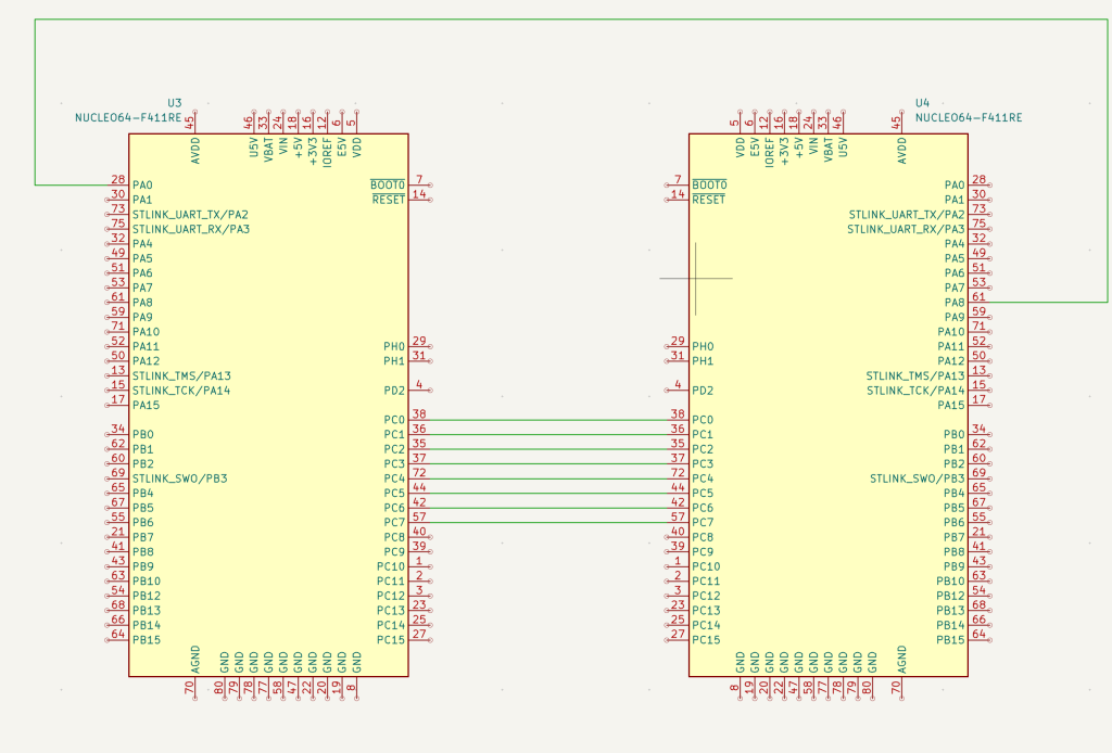
3. Connection of Two STM32s:
The parallel connection as following:
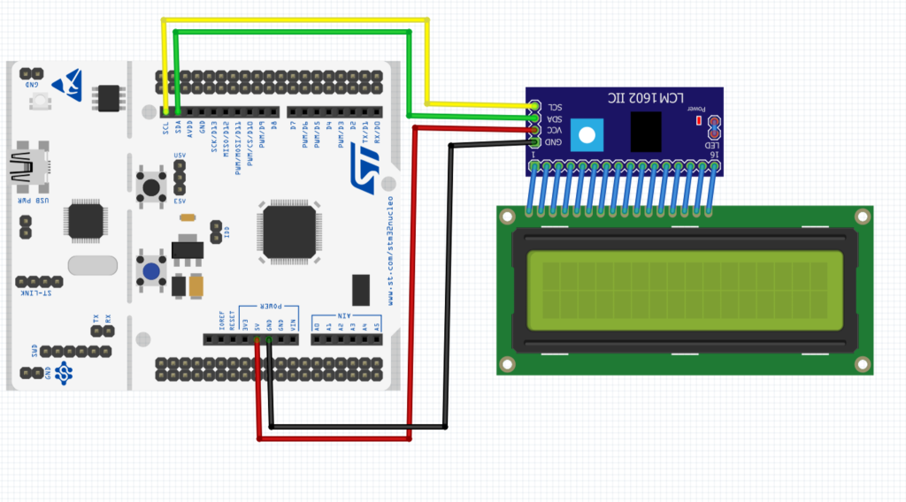
For the LCD connection:
4. Code:
You may download the both code from here:
Transmitter code:
Receiver code (For F446RE):
5. Results:
As you can see, we have successfully transmitted the data and received it.
Now the question is, when the transmitter transfer the number 400, why the receiver received 144?
Share your answer in comments.
Happy coding 😉
Add Comment