
In this first section of the fourteenth part of board support package on STM32F411, we shall develop the initialization function of I2C and build I2C bus scanner to get the address of the connected slave devices.
In this guide, we shall cover the following:
- Developing the header file.
- Developing the source file.
- Main code.
- Results.
1. Developing the header file:
Before we start developing the header file, take a look at this guide (here) to find more information about about I2C and how to configure it from scratch.
We start off with creating new header file with name of i2c_bsp.h file.
Within the header, include the header file guard:
#ifndef I2C_BSP_H_
#define I2C_BSP_H_


#endif
Within the header guard, include the following header files:
#include "stm32f4xx.h"
#include "stdint.h"
#include "bsp_debug.h"
#include "bsp.h"
Since STM32F411 features 3 I2Cs bus, we shall use micros to enable clock access to each peripheral:
#define __I2C1_CLOCK_ENABLE()		RCC->APB1ENR|=RCC_APB1ENR_I2C1EN
#define __I2C2_CLOCK_ENABLE()		RCC->APB1ENR|=RCC_APB1ENR_I2C2EN
#define __I2C3_CLOCK_ENABLE()		RCC->APB1ENR|=RCC_APB1ENR_I2C3EN
Since I2C can operate on either, standard speed (100KHz) or fast mode (400KHz), we shall create enum for the following states as following:
typedef enum
{
	standardSpeed=0,
	fastMode=1
}I2C_MasterModeTypedef;
Since there is two type of duty mode in fast mode, t low /t high = 2 or t low /t high = 16/9. Hence, we shall create enum to handle both cases:
typedef enum
{
	Duty_2=0,
	Duty_16_9=1
}I2C_DutyModeTypedef;
For status of the I2C, we shall create enum to handle three states as following:
- Success.
- Failed.
- Timeout.
typedef enum
{
	i2c_success=0,
	i2c_failed=1,
	i2c_timeOut=2
}I2C_StatusTypedef;
This will become handy in the next section of the guide.
Create new data structure to configure the I2C peripheral:
typedef struct
{

	uint8_t PeripheralFrequency;

	uint8_t MasterMode;

	uint8_t DutyMode;

	uint16_t RiseTime;

	uint16_t Clock;

}I2C_ConfigTypedef;
The parameters as following:
- Peripheral Frequency which is the peripheral bus frequency connected to (APB1 in this case).
- Master Mode to choose either standard or fast speed mode.
- Duty mode for type of duty.
- Rise time for the rise time of SCL and SDA line.
- Clock to generate the correct frequency of SCL.
Declare the following function:
void BSP_I2C_Init(I2C_TypeDef *i2c, I2C_ConfigTypedef *config);
This function shall initialize the I2C peripheral and take I2C Typedef struct for which I2C and config struct to handle the configuration and returns nothing.
Also, declare the following function:
void BSP_I2C_Bus_Scan(I2C_TypeDef *i2c);
This will scan the I2C bus for the connected peripheral and takes I2C_Typedef as argument and return nothing.
Hence, the entire header file as following:
#ifndef I2C_BSP_H_
#define I2C_BSP_H_

#include "stm32f4xx.h"
#include "stdint.h"
#include "bsp_debug.h"
#include "bsp.h"

#define __I2C1_CLOCK_ENABLE()		RCC->APB1ENR|=RCC_APB1ENR_I2C1EN
#define __I2C2_CLOCK_ENABLE()		RCC->APB1ENR|=RCC_APB1ENR_I2C2EN
#define __I2C3_CLOCK_ENABLE()		RCC->APB1ENR|=RCC_APB1ENR_I2C3EN

i2c_bsp.c
typedef enum
{
	standardSpeed=0,
	fastMode=1
}I2C_MasterModeTypedef;


typedef enum
{
	Duty_2=0,
	Duty_16_9=1
}I2C_DutyModeTypedef;


typedef enum
{
	i2c_success=0,
	i2c_failed=1,
	i2c_timeOut=2
}I2C_StatusTypedef;


typedef struct
{

	uint8_t PeripheralFrequency;

	uint8_t MasterMode;

	uint8_t DutyMode;

	uint16_t RiseTime;

	uint16_t Clock;

}I2C_ConfigTypedef;


void BSP_I2C_Init(I2C_TypeDef *i2c, I2C_ConfigTypedef *config);

void BSP_I2C_Bus_Scan(I2C_TypeDef *i2c);

#endif /* I2C_BSP_H_ */
2. Developing the source code:
Create new source code file with name of i2c_bsp.c.
Within the source file, include the following:
#include "i2c_bsp.h"
For the initialization function:
void BSP_I2C_Init(I2C_TypeDef *i2c, I2C_ConfigTypedef *config)
Start by reseting the peripheral and release it from reset state as following:
	i2c->CR1=I2C_CR1_SWRST;

	i2c->CR1&=~I2C_CR1_SWRST;
Set the peripheral frequency as following:
i2c->CR2|= config->PeripheralFrequency;
Set the rise time:
i2c->TRISE=config->RiseTime;
Set the master mode:
i2c->CCR|=(config->MasterMode<<I2C_CCR_FS_Pos);
Set the duty mode:
i2c->CCR|=(config->DutyMode<<I2C_CCR_DUTY_Pos);
Now to set the clock to generate the required SCL frequency as following:
In case the user didn’t set the clock, the BSP shall calculate it automatically as following:
	if((config->Clock)==0)
	{
		float period =1.0/(float)(config->PeripheralFrequency);

		if((config->MasterMode)==standardSpeed)
		{

			uint16_t tmp = 5/period;
			i2c->CCR|=(tmp<<I2C_CCR_CCR_Pos);
		}

		else
		{
			if(config->DutyMode==Duty_2)
			{
				uint16_t tmp=1.25/period;
				i2c->CCR|=(tmp<<I2C_CCR_CCR_Pos);
			}

			else
			{
				uint16_t tmp=(1.25*9)/period;
				i2c->CCR|=(tmp<<I2C_CCR_CCR_Pos);
			}
		}


	}
We start by calculating the period by dividing 1 over the peripheral frequency.
if the mode is standard:
Since the frequency is 100KHz, and the period is 5us, we can get the CCR to be 5 over the period.
If the mode is fast mode,
You have two modes, low /t high = 2 or t low /t high = 16/9.
When duty mode is low /t high = 2:
uint16_t tmp=1.25/period;
i2c->CCR|=(tmp<<I2C_CCR_CCR_Pos);
When low /t high = 16/9:
uint16_t tmp=(1.25*9)/period;
i2c->CCR|=(tmp<<I2C_CCR_CCR_Pos);
If the user wants custom CCR value:
	else
	{
		i2c->CCR|=(config->Clock<<I2C_CCR_CCR_Pos);
	}
Finally, enable the peripheral:
i2c->CR1|=I2C_CR1_PE;
Hence, the initializing function as following:
void BSP_I2C_Init(I2C_TypeDef *i2c, I2C_ConfigTypedef *config)
{

	i2c->CR1=I2C_CR1_SWRST;

	i2c->CR1&=~I2C_CR1_SWRST;

	i2c->CR2|= config->PeripheralFrequency;

	i2c->TRISE=config->RiseTime;

	i2c->CCR|=(config->MasterMode<<I2C_CCR_FS_Pos);

	i2c->CCR|=(config->DutyMode<<I2C_CCR_DUTY_Pos);

	if((config->Clock)==0)
	{
		float period =1.0/(float)(config->PeripheralFrequency);

		if((config->MasterMode)==standardSpeed)
		{

			uint16_t tmp = 5/period;
			i2c->CCR|=(tmp<<I2C_CCR_CCR_Pos);
		}

		else
		{
			if(config->DutyMode==Duty_2)
			{
				uint16_t tmp=5/period;
				i2c->CCR|=(tmp<<I2C_CCR_CCR_Pos);
			}

			else
			{
				uint16_t tmp=13/period;
				i2c->CCR|=(tmp<<I2C_CCR_CCR_Pos);
			}
		}


	}
	else
	{
		i2c->CCR|=(config->Clock<<I2C_CCR_CCR_Pos);
	}

	i2c->CR1|=I2C_CR1_PE;

}
For the i2c scan bus function:
void BSP_I2C_Bus_Scan(I2C_TypeDef *i2c)
{
	char data[100];
	uint8_t a=0;
	for (uint8_t i=0;i<128;i++)
	{
		i2c->CR1 |= I2C_CR1_START;
		while(!(i2c->SR1 & I2C_SR1_SB));
		i2c->DR=(i<<1|0);
		while(!(i2c->SR1)|!(I2C1->SR2)){};
		i2c->CR1 |= I2C_CR1_STOP;
		BSP_Delay(1);
		a=(i2c->SR1&I2C_SR1_ADDR);
		if (a==2)
	    {
			sprintf(data,"Found I2C device at address 0x%X (hexadecimal), or %d (decimal)\n\r",i,i);
			log_info(data);
	    }
	 }
}
Hence, the entire source file as following:
#include "i2c_bsp.h"


void BSP_I2C_Init(I2C_TypeDef *i2c, I2C_ConfigTypedef *config)
{

	i2c->CR1=I2C_CR1_SWRST;

	i2c->CR1&=~I2C_CR1_SWRST;

	i2c->CR2|= config->PeripheralFrequency;

	i2c->TRISE=config->RiseTime;

	i2c->CCR|=(config->MasterMode<<I2C_CCR_FS_Pos);

	i2c->CCR|=(config->DutyMode<<I2C_CCR_DUTY_Pos);

	if((config->Clock)==0)
	{
		float period =1.0/(float)(config->PeripheralFrequency);

		if((config->MasterMode)==standardSpeed)
		{

			uint16_t tmp = 5/period;
			i2c->CCR|=(tmp<<I2C_CCR_CCR_Pos);
		}

		else
		{
			if(config->DutyMode==Duty_2)
			{
				uint16_t tmp=5/period;
				i2c->CCR|=(tmp<<I2C_CCR_CCR_Pos);
			}

			else
			{
				uint16_t tmp=13/period;
				i2c->CCR|=(tmp<<I2C_CCR_CCR_Pos);
			}
		}


	}
	else
	{
		i2c->CCR|=(config->Clock<<I2C_CCR_CCR_Pos);
	}

	i2c->CR1|=I2C_CR1_PE;

}


void BSP_I2C_Bus_Scan(I2C_TypeDef *i2c)
{
	char data[100];
	uint8_t a=0;
	for (uint8_t i=0;i<128;i++)
	{
		i2c->CR1 |= I2C_CR1_START;
		while(!(i2c->SR1 & I2C_SR1_SB));
		i2c->DR=(i<<1|0);
		while(!(i2c->SR1)|!(I2C1->SR2)){};
		i2c->CR1 |= I2C_CR1_STOP;
		BSP_Delay(1);
		a=(i2c->SR1&I2C_SR1_ADDR);
		if (a==2)
	    {
			sprintf(data,"Found I2C device at address 0x%X (hexadecimal), or %d (decimal)\n\r",i,i);
			log_info(data);
	    }
	 }
}
3. Main code:
Within main.c:
Include the i2c_bsp header file as following:
#include "i2c_bsp.h"
Declare the configuration structure as following:
I2C_ConfigTypedef i2c1Config;
In main function:
Configure PB8 and PB9 as alternate function with open drain and pullup resistors with AF4:
	GPIO_Configure_Typedef I2C_PB8, I2C_PB9;

	GPIOB_CLOCK_ENABLE();

	I2C_PB8.PinNumber=8;
	I2C_PB8.OutputType=Open_Drain;
	I2C_PB8.Mode=Alternate_function;
	I2C_PB8.PullUp_PullDown=PullUp;
	I2C_PB8.AlternateType=AF4;

	I2C_PB9.PinNumber=9;
	I2C_PB9.OutputType=Open_Drain;
	I2C_PB9.Mode=Alternate_function;
	I2C_PB8.PullUp_PullDown=PullUp;
	I2C_PB9.AlternateType=AF4;

	GPIO_Initialization(GPIOB,&I2C_PB8);
	GPIO_Initialization(GPIOB,&I2C_PB9);
Enable clock access to I2C1:
__I2C1_CLOCK_ENABLE();
Configure the I2C1 as following:
	i2c1Config.MasterMode=standardSpeed;

	i2c1Config.PeripheralFrequency=50;

	i2c1Config.RiseTime=9;

	BSP_I2C_Init(I2C1, &i2c1Config);
In while one loop:
	while(1)
	{
		BSP_I2C_Bus_Scan(I2C1);
		BSP_Delay(200);
	}
Hence, the entire main.c file:
#include "bsp.h"
#include "uart_bsp.h"
#include "exti_bsp.h"
#include "bsp_debug.h"
#include "spi_bsp.h"
#include "dma_bsp.h"
#include "i2c_bsp.h"
#include "stdlib.h"

void clock_config(void);

I2C_ConfigTypedef i2c1Config;


int main()
{


	#if FPU_EN
		SCB->CPACR |= ((3UL << 10*2)|(3UL << 11*2));
	#endif

	clock_config();
	BSP_Ticks_Init(100000000);

	GPIO_Configure_Typedef I2C_PB8, I2C_PB9;

	GPIOB_CLOCK_ENABLE();

	I2C_PB8.PinNumber=8;
	I2C_PB8.OutputType=Open_Drain;
	I2C_PB8.Mode=Alternate_function;
	I2C_PB8.PullUp_PullDown=PullUp;
	I2C_PB8.AlternateType=AF4;

	I2C_PB9.PinNumber=9;
	I2C_PB9.OutputType=Open_Drain;
	I2C_PB9.Mode=Alternate_function;
	I2C_PB8.PullUp_PullDown=PullUp;
	I2C_PB9.AlternateType=AF4;

	GPIO_Initialization(GPIOB,&I2C_PB8);
	GPIO_Initialization(GPIOB,&I2C_PB9);

	__I2C1_CLOCK_ENABLE();

	i2c1Config.MasterMode=standardSpeed;

	i2c1Config.PeripheralFrequency=50;

	i2c1Config.RiseTime=9;

	BSP_I2C_Init(I2C1, &i2c1Config);


	while(1)
	{
		BSP_I2C_Bus_Scan(I2C1);
		BSP_Delay(200);
	}
}

void clock_config(void)
{
	Clock_Config_Typedef clockConfig;

	clockConfig.PLL_M= 4;
	clockConfig.PLL_N= 200;
	clockConfig.PLL_P= 4;

	clockConfig.AHB1Prescaler=AHB1_Prescaler1;
	clockConfig.APB1Prescaler=APB1_Prescaler2;
	clockConfig.APB2Prescaler=APB2_Prescaler1;

	clockConfig.clockSourc=External_Oscillator;
	clockConfig.flash_latency= Three_wait_state;

	Clock_Configuration(&clockConfig);
}
4. Results:
In order to see the results, you need to configure SWO as shown in this guide here.
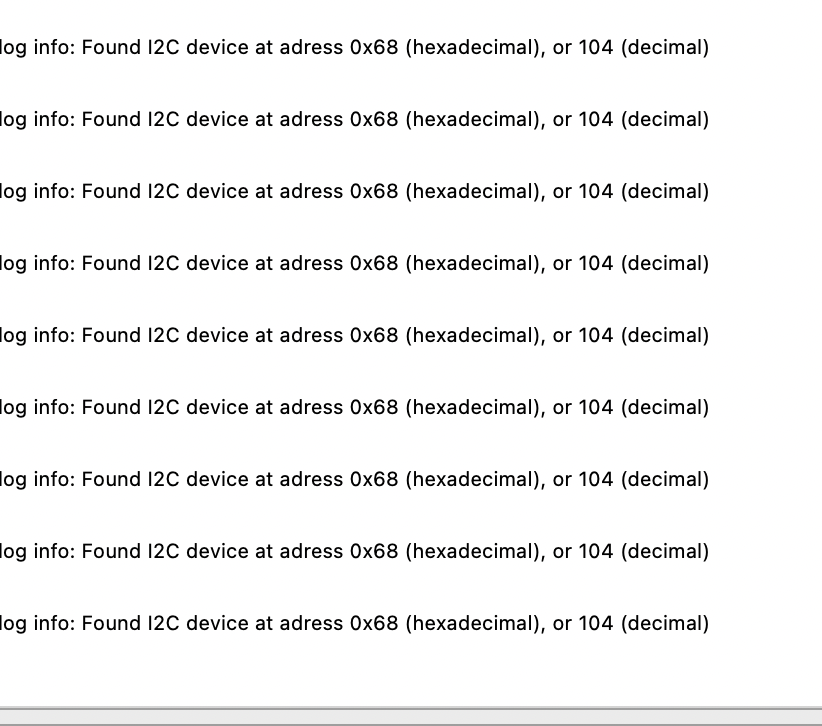
You should get the addresses of attached slave devices (1 in this case):
Happy coding 🙂
Add Comment