
In the previous part of this guide (here), we took a look at how to configure the SysTick to generate ticks for the system for timing, delay etc. Also, in part 1 (here), we saw how to configure the GPIO in analog mode, input and output. In this guide, we shall see how to configure the pin in alternate functuon.
In this guide, we shall cover the following:
- GPIO configuration in alternate mode.
- Code.
- Results.
1. GPIO Configuration in alternate function:
Within the following function , bsp.c source code:
void GPIO_Initialization(GPIO_TypeDef *GPIO,GPIO_Configure_Typedef * GPIO_Config)
We shall check if the pin mode is alternate function as following:
if (GPIO_Config->Mode == Alternate_function)
If it is, set the required pin mode to 00 (general purpose input) as following:
GPIO->MODER &=~((0x03<<(GPIO_Config->PinNumber*2)));
Set the mode:
GPIO->MODER|= (GPIO_Config->Mode<< GPIO_Config->PinNumber*2);
Set the following:
- Speed.
- Pull up pull down.
- Output type.
		GPIO->OTYPER|= (GPIO_Config->OutputType<<GPIO_Config->PinNumber);

		GPIO->OSPEEDR|= (GPIO_Config->OutPutspeed<< GPIO_Config->PinNumber*2);

		GPIO->PUPDR|= (GPIO_Config->PullUp_PullDown<< GPIO_Config->PinNumber*2);
Now, we shall set the type of the alternate function.
First check if the pin between 0 and 7 or between 8 and 15.
The reason behind this checking since the AFR register is divided in low and high part as following:
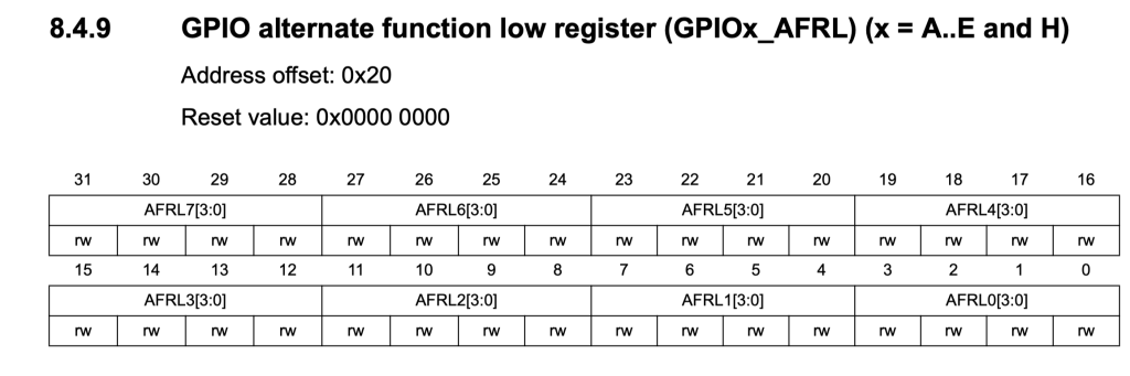
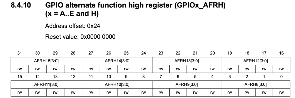
The low will handle the pins from 0 to 7 while high part will handle pins from 8 to 15.
First if the pin between pin 0 and pin 7:
		if (GPIO_Config->PinNumber <=pin7)
		{
			GPIO->AFR[0]= (GPIO_Config->AlternateType << GPIO_Config->PinNumber *4);
		}
Since the settings is 4-bit wide, we shall multiply the pin number by 4 which will set the required pin to alternate number function.
If the pin between 8 and 15:
		if (GPIO_Config->PinNumber>pin7 && GPIO_Config->PinNumber<=pin15)
		{
			GPIO->AFR[1]= (GPIO_Config->AlternateType << (GPIO_Config->PinNumber-8) *4);
		}
Hence, the part of alternate function as following:
	if (GPIO_Config->Mode == Alternate_function)
	{
		GPIO->MODER &=~((0x03<<(GPIO_Config->PinNumber*2)));
		GPIO->MODER|= (GPIO_Config->Mode<< GPIO_Config->PinNumber*2);

		GPIO->OTYPER|= (GPIO_Config->OutputType<<GPIO_Config->PinNumber);

		GPIO->OSPEEDR|= (GPIO_Config->OutPutspeed<< GPIO_Config->PinNumber*2);

		GPIO->PUPDR|= (GPIO_Config->PullUp_PullDown<< GPIO_Config->PinNumber*2);

		if (GPIO_Config->PinNumber <=pin7)
		{
			GPIO->AFR[0]= (GPIO_Config->AlternateType << GPIO_Config->PinNumber *4);
		}

		if (GPIO_Config->PinNumber>pin7 && GPIO_Config->PinNumber<=pin15)
		{
			GPIO->AFR[1]= (GPIO_Config->AlternateType << (GPIO_Config->PinNumber-8) *4);
		}

	}
2. Code:
You may get the code from this github repository:
Board-Support-Package-for-STM32F411RE-Nucleo64
3. Results:
For testing purposes, we shall set PA2 and PA9 to alternate function AF7 as following in main.c:
GPIO_Configure_Typedef PA2_ALT;

	PA2_ALT.PinNumber=pin2;
	PA2_ALT.Mode=Alternate_function;
	PA2_ALT.AlternateType=AF7;

	GPIO_Initialization(GPIOA,&PA2_ALT);


	GPIO_Configure_Typedef PA9_ALT;

	PA9_ALT.PinNumber=pin9;
	PA9_ALT.Mode=Alternate_function;
	PA9_ALT.AlternateType=AF7;

	GPIO_Initialization(GPIOA,&PA9_ALT);
From debugging session we can see that PA2 and PA7 are set to alternate function and AF7 as following:
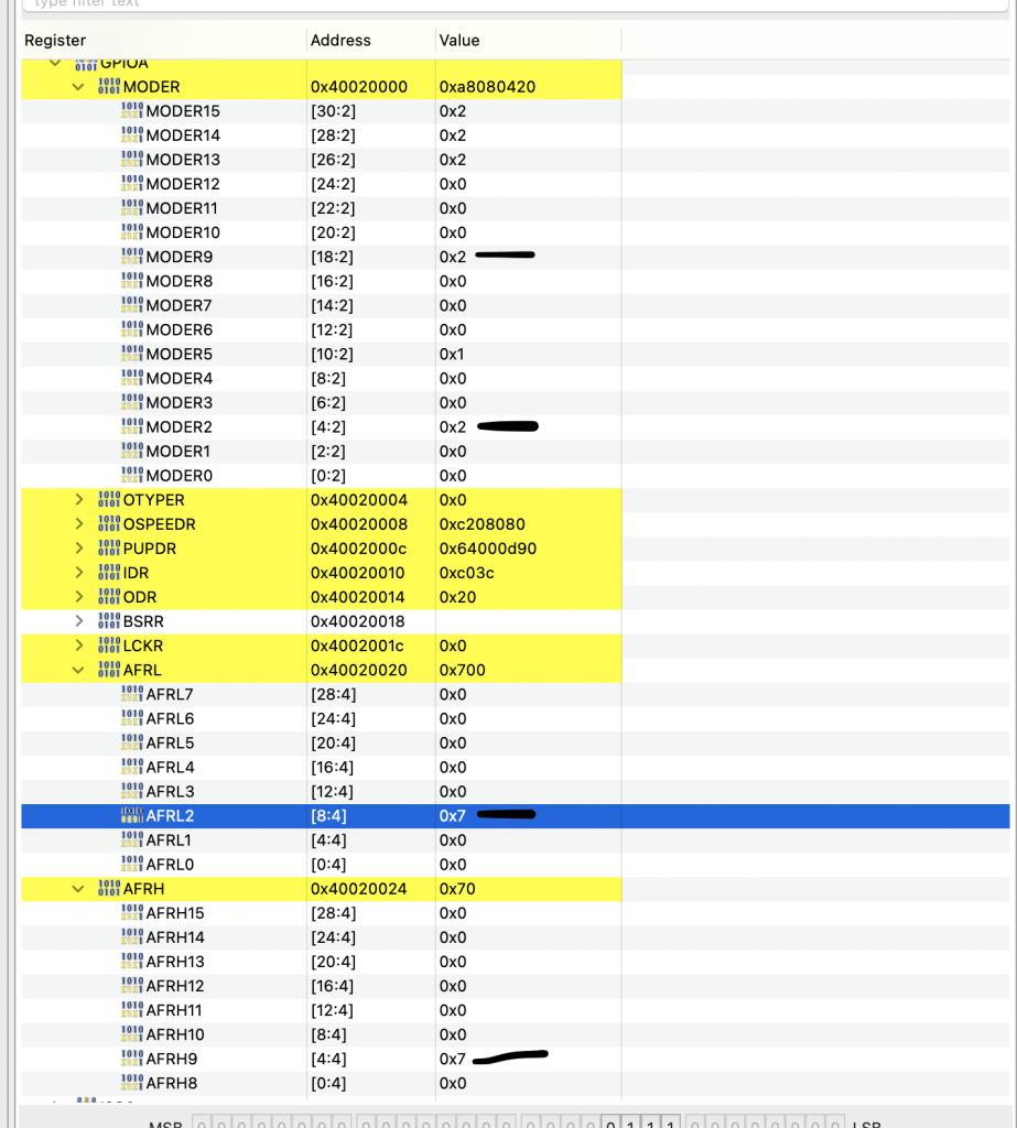
Happy coding 🙂
Add Comment