In the previous guide (here), we saw how to configure the ADC with DMA and timer to trigger it periodically. In this guide, we shall see how to use the double buffer mode to increase the potential processing power of STM32F4.
In this guide, we shall cover the following:
- Double Buffer mode.
- ADC and DMA configuration.
- Process the buffers.
- Code.
- Results.
1. Double Buffer Mode:
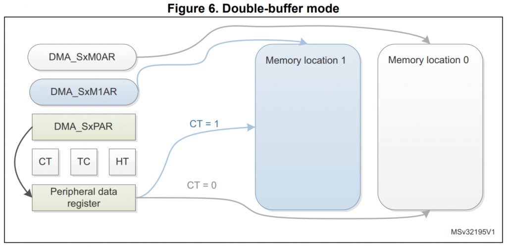
A double-buffer stream works as a regular (single buffer) stream with the difference that it has two memory pointers. When the Double buffer mode is enabled, the Circular mode is automatically enabled (CIRC bit in DMA_SxCR is don’t care) and at each end of transaction, the memory pointers are swapped.
In this mode, the DMA controller swaps from one memory target to another at each end of transaction. This allows the software to process one memory area while the second memory area is being filled/used by the DMA transfer. The double-buffer stream can work in both directions.
2. ADC and DMA configuration:
For detailed ADC configuration, please refer to this guide here.
We start off by creating new source and header file with name of adc.c and adc.h respectively.
Within the header:
#ifndef ADC_H_
#define ADC_H_

#include "stdint.h"

void adc_init(void);
uint8_t buffer_filled();
void print_buffer();


#endif /* ADC_H_ */
The header file contain the following functions:
- ADC and DMA initializing.
- Check if the buffer is filled.
- Print the buffer (as buffer process).
Thats all for the header file.
Within the source file:
Include the following:
#include "adc.h"
#include "stm32f4xx.h"                  // Device header
#include "stdio.h"
Declare two buffers to hold the adc values:
uint16_t adc_data1[10];
uint16_t adc_data2[10];
volatile variable to indicate finish of filling the buffer:
volatile uint8_t finished=0;
Within the adc_init function:
Setting PA0 as analog mode:
	RCC->AHB1ENR		|=RCC_AHB1ENR_GPIOAEN;
	GPIOA->MODER		|=GPIO_MODER_MODE0_0|GPIO_MODER_MODE0_1;
ADC Configuration with DMA and timer trigger:
	RCC->APB2ENR		|=RCC_APB2ENR_ADC1EN;
	ADC1->CR2			|=ADC_CR2_DMA|ADC_CR2_DDS;
	ADC1->CR2			|=ADC_CR2_EXTEN_0;
	ADC1->CR2			|=ADC_CR2_EXTSEL_1|ADC_CR2_EXTSEL_2;
DMA Configuration:
The DMA configuration as following:
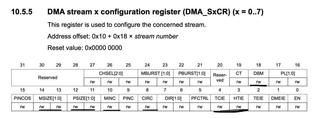
- Memory and peripheral size to be half-word (16-bit).
- Memory increment mode.
- Half and transfer complete interrupt enable.
- Double buffer mode.
/*DMA related setup*/
	RCC->AHB1ENR		|=RCC_AHB1ENR_DMA2EN;
	DMA2_Stream0->CR	&=~DMA_SxCR_EN;
	while(DMA2_Stream0->CR ==DMA_SxCR_EN){;}

	DMA2_Stream0->CR	|=DMA_SxCR_MSIZE_0|DMA_SxCR_PSIZE_0|
			DMA_SxCR_MINC|DMA_SxCR_TCIE|DMA_SxCR_HTIE
			|DMA_SxCR_CIRC|DMA_SxCR_DBM;
Set the peripheral address to ADC1->DR:
DMA2_Stream0->PAR =(uint32_t)(&(ADC1->DR));
Set memory0 and memory1 address to the two buffer:
	DMA2_Stream0->M0AR 	 =(uint32_t )(adc_data1);
	DMA2_Stream0->M1AR 	 =(uint32_t )(adc_data2);
Set the number of transfers to be size of the buffers (10 in this case):
DMA2_Stream0->NDTR =10;
Enable DMA2_Stream0 interrupt in NVIC:
NVIC_EnableIRQ(DMA2_Stream0_IRQn);
Configure the timer:
	/* Timer related setup*/
	RCC->APB1ENR		|=RCC_APB1ENR_TIM2EN;
	TIM2->PSC			 =16000-1;
	TIM2->ARR			 =10-1;
	TIM2->CR2			|=TIM_CR2_MMS_1;
Launch the peripheral at this order:
- ADC.
- DMA.
- Timer.
/*Launch the ADC*/
	ADC1->CR2			|=ADC_CR2_ADON;
	/*Launch the DMA*/
	DMA2_Stream0->CR 	|=DMA_SxCR_EN;
	/*Launch the timer*/
	TIM2->CR1			|=TIM_CR1_CEN;
For the interrupt handler:
Check the interrupt source:
- Half transfer-> Set finished to 1 and clear the relevant flag
- Transfer Complete-> Set finished to 1 and clear the relevant flag.
void DMA2_Stream0_IRQHandler(void)
{

	if(((DMA2->LISR)&DMA_LISR_TCIF0))
	{
		finished=1;
		DMA2->LIFCR=DMA_LIFCR_CTCIF0;
	}

	if(((DMA2->LISR)&DMA_LISR_HTIF0))
	{
		finished=1;
		DMA2->LIFCR=DMA_LIFCR_CHTIF0;
	}

}
3. Process the buffer:
Before we process the buffer, we need to check if any buffer is filled by check the finished variable:
uint8_t buffer_filled()
{
	return finished;
}
If finished is 1, process the buffer.
To determine which buffer is filled, we need to check the CT (Current Target) bit in the CR register of the DMA as following:
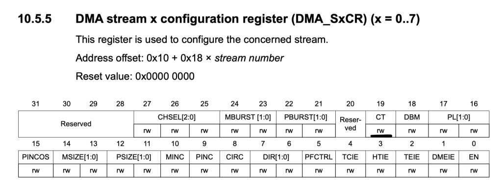
- CT is 1 -> Buffer1 is filled.
- CT is 0 -> Buffer2 is filled.
void print_buffer()
{

	finished=0;

	if ((DMA2_Stream0->CR & DMA_SxCR_CT)) /*If true, adc_data1 is filled */
	{
		printf("ADC Buffer1 data are:\r\n");
		for(int i=0;i<10;i++)
		{
			printf("%d\t",adc_data1[i]);
		}
		printf("\r\n");
	}

	else
	{
		printf("ADC Buffer2 data are:\r\n");
		for(int i=0;i<10;i++)
		{
			printf("%d\t",adc_data2[i]);
		}
		printf("\r\n");

	}

}
The process is simple which is printing the buffer, in your application, you can do what ever you want like finding the difference between both value, calculate the RMS, etc.
within main.c:
#include "uart.h"
#include "adc.h"


int main()
{

	uart2_init();
	adc_init();


	while(1)
	{
		if(buffer_filled()) /*Check if the buffer is filled*/
		{
			/*Process the buffer (print in this case)*/
			print_buffer();
		}
	}


}
Hence the entire source code as following:
/*
 * adc.c
 *
 *  Created on: Jun 24, 2023
 *      Author: hussamaldean
 */


#include "adc.h"
#include "stm32f4xx.h"                  // Device header
#include "stdio.h"


uint16_t adc_data1[10];
uint16_t adc_data2[10];
volatile uint8_t finished=0;


void adc_init(void)
{
	/*ADC related set up*/
	RCC->AHB1ENR		|=RCC_AHB1ENR_GPIOAEN;
	GPIOA->MODER		|=GPIO_MODER_MODE0_0|GPIO_MODER_MODE0_1;

	RCC->APB2ENR		|=RCC_APB2ENR_ADC1EN;
	ADC1->CR2			|=ADC_CR2_DMA|ADC_CR2_DDS;
	ADC1->CR2			|=ADC_CR2_EXTEN_0;
	ADC1->CR2			|=ADC_CR2_EXTSEL_1|ADC_CR2_EXTSEL_2;

	/*DMA related setup*/
	RCC->AHB1ENR		|=RCC_AHB1ENR_DMA2EN;
	DMA2_Stream0->CR	&=~DMA_SxCR_EN;
	while(DMA2_Stream0->CR ==DMA_SxCR_EN){;}

	DMA2_Stream0->CR	|=DMA_SxCR_MSIZE_0|DMA_SxCR_PSIZE_0|
			DMA_SxCR_MINC|DMA_SxCR_TCIE|DMA_SxCR_HTIE
			|DMA_SxCR_CIRC|DMA_SxCR_DBM;

	DMA2_Stream0->PAR	 =(uint32_t)(&(ADC1->DR));
	DMA2_Stream0->M0AR 	 =(uint32_t )(adc_data1);
	DMA2_Stream0->M1AR 	 =(uint32_t )(adc_data2);
	DMA2_Stream0->NDTR	 =10;

	NVIC_EnableIRQ(DMA2_Stream0_IRQn);

	/* Timer related setup*/
	RCC->APB1ENR		|=RCC_APB1ENR_TIM2EN;
	TIM2->PSC			 =16000-1;
	TIM2->ARR			 =10-1;
	TIM2->CR2			|=TIM_CR2_MMS_1;
	/*Launch the ADC*/
	ADC1->CR2			|=ADC_CR2_ADON;
	/*Launch the DMA*/
	DMA2_Stream0->CR 	|=DMA_SxCR_EN;
	/*Launch the timer*/
	TIM2->CR1			|=TIM_CR1_CEN;
}


uint8_t buffer_filled()
{
	return finished;
}


void print_buffer()
{

	finished=0;

	if ((DMA2_Stream0->CR & DMA_SxCR_CT)) /*If true, adc_data1 is filled */
	{
		printf("ADC Buffer1 data are:\r\n");
		for(int i=0;i<10;i++)
		{
			printf("%d\t",adc_data1[i]);
		}
		printf("\r\n");
	}

	else
	{
		printf("ADC Buffer2 data are:\r\n");
		for(int i=0;i<10;i++)
		{
			printf("%d\t",adc_data2[i]);
		}
		printf("\r\n");

	}

}


void DMA2_Stream0_IRQHandler(void)
{

	if(((DMA2->LISR)&DMA_LISR_TCIF0))
	{
		finished=1;
		DMA2->LIFCR=DMA_LIFCR_CTCIF0;
	}

	if(((DMA2->LISR)&DMA_LISR_HTIF0))
	{
		finished=1;
		DMA2->LIFCR=DMA_LIFCR_CHTIF0;
	}

}
4. Code:
You may download the source code from here:
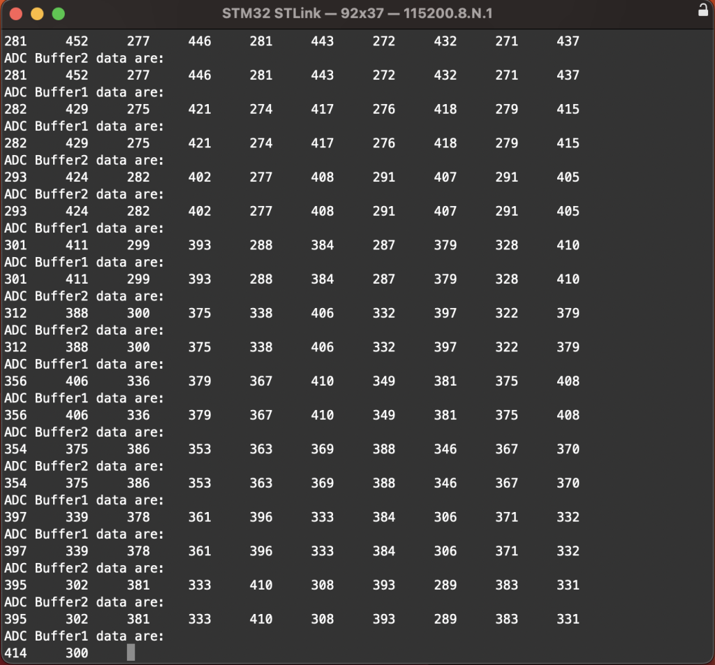
5. Results:
Open serial terminal program and set the baud rate to 115200 and you should get the following:
Happy coding 😊😊
Add Comment